The excellent cutting experience with extra-fine-grain materials is also a result of the high sintering quality with low variation in composite density and a highly homogeneous structure as a result of the sintering process of extra-fine-grain carbide particles.
Cutting Tool Coating and Cutting Edge Rounding
The purpose of cutting tool coating in the area of chip forming action is to provide a surface layer with high hardness and low surface roughness. This protects the carbide cutting edge and surroundings from chemical reactions and isolates the basic substrate from the chip flow with respect to wear and temperature.
It seems to be a basically different task to protect the cutting edge of a two-face sharpened blade vs. the cutting edge of a three-face sharpened blade. The three-face sharpening requires an all-around coating, which delivers a cutting edge that is formed by a coated front face, as well as a coated side-relief surface including top relief area and also covering the clearance side surface.
The blade that is only coated on the front face (two-face sharpened blade as shown in Figure 2) has a protection on the front face, where the surface stress from chip forming is the highest, and where the chips are being molded to their final form with a high relative surface speed. The unprotected side relief surface has a continuous sliding contact with the flank surface of the work. The individual parameters of a particular cutting process will make the difference between high contact forces that lead to rapid wear and cutting edge chipping or a result in a negligible side relief wear with an un-chipped appearance of the cutting edge (Ref. 2).
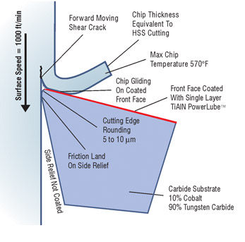
Figure 2—Chip removal mechanics.
The edge-rounding radius dimension and the micro blend between edge rounding and front face coating are the key parameters to achieve low cutting forces, optimal plasticization and chip shearing action. The optimal edge-rounding radius for today’s high-speed dry cutting for only front-face-coated blades lies between 5 µm and 10 µm. Figure 3 shows, on the left side, a device for edge rounding of carbide blades with permanent front face coating. The nylon bristles of a rotating brush contain aluminum oxide. The brush traverses sideways while it is rotating with a circumferential velocity vector that is lined up in the 3–7 mm interference zone between cutting edge and brush with the direction of the cutting edge. The photographs on the right side of Figure 3 show on top the cutting edge before edge rounding, and the photos below show the cutting edge after rounding. The upper section in the photographs with the darker color is the coated front face, the light colored stripe is the cutting edge and the area below is the side relief surface. The influence of edge rounding is evident by the reduced micro craters and the smoother transition between the cutting edge and the coating.
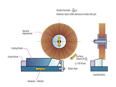
Figure 3—Edge rounding device and cutting edge before and after rounding.
At the beginning of carbide dry cutting operations, the best cutting results were obtained using a TiAlN coating with a composition of 50% Titanium and 50% Aluminum-Nitride.
Both single- and multi-layer coatings were tested in many cutting trials. Today, the commonly used and highest performing coatings are derivatives of a single 10 µm-thick layer of TiAlN with the trade names AlNite® and TiAln-X. The coating table in Figure 4 gives an overview of some physical properties of coatings in use today for chip removing operations (Ref. 1).
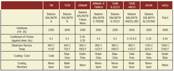
Figure 4—Table with commonly used physical vapor deposition (PVD) coating types.
Workpiece Material and Structural Treatment
Gears in industrial gear boxes and automotive/truck transmissions are generally manufactured from carburizing steels, which provide a hard and highly durable surface and a core with high toughness after case hardening. Commonly used materials for manufacturing of bevel gears are:
A) AISI 5117 or ISO 16MnCr5 with tensile strength 600 N/mm2
B) AISI 3215 or ISO 18CrNiMo6 with tensile strength 800 N/mm2
C) AISI 4119 or ISO 20MoCr4 with tensile strength 700 N/mm2
AISI 5117 provides best machinability and behaves well during heat treat and quenching with respect to distortion, internal stresses and the mechanical properties of surface and core.
AISI 3215 delivers high core hardness after heat treatment (above 40 HRC), is sensitive to heat treat distortions and is critical with respect to tool life.
AISI 4119 cannot provide the same high mechanical properties as AISI 3215, but shows better machinibility. It is often used as a compromise between AISI 5117 and AISI 3215.
Manufacturing of small batch production is mostly done from bar stock material. In a mass production environment, the blank material is forged to a shape that approximates the turned blank contour closely with a decent stock allowance. In both cases, the steel structure is not optimal with respect to machinability and should be annealed or normalized.
The photographs in Figure 5 show the structure of a forged blank after etching with nitric acid with a magnification of 200x. The left photograph in Figure 5 shows a coarse structure from ferrite with little but concentrated grain borders of pearlite and graphite.

Figure 5—Steel structure of a forged blank (left), after normalizing (center) and after annealing (right).
Although the structure will change during the case hardening and quenching process to provide the desired properties of the finished gear, turning and cutting of the soft material according to the left photo in Figure 5 will deliver medium to low tool life.
For optimal cutting performance with respect to surface finish and tool life for both high-speed steel wet cutting or carbide dry cutting, it is recommended to change the structure to a more homogeneous appearance with a smaller ferrite grain size. The result of normalizing is shown in the center of Figure 5. The right side photograph shows the fine structure after annealing the forged material. Forming a chip means generating a crack through the structures shown in the three photos. Such a crack will follow the softer graphite, which is between the hard ferrite particles. It is obvious that, in case of a very coarse structure, the cutting edges frequently hit large ferrite particles. In some cases, this splits the ferrite but more likely will move the large ferrite particles out of its way, which causes extensive wear of the cutting edge and results in a rough surface finish. An extremely fine structure will cause edge build-up and tearing with a scuffed- appearing surface finish.
Optimal for dry high-speed machining with carbide is a structure between the center and right-hand-side photo (Figure 5).
Feeds and Speeds
The original surface speed recommendation of 330 m/min for high-speed carbide bevel gear cutting came from cylindrical gear hobbing with carbide hobs. At the beginning of high-speed bevel gear cutting, it became evident that the chip thickness has to exceed a certain minimum value to reduce cutting edge chipping and abrasive wear on the side relief surface. In other words, it was not only possible to use large chip thicknesses in high-speed bevel gear cutting but it proved to be required in order to achieve good and consistent tool life. Figure 6 shows the dependency between chip thickness, surface speed and tool wear as a qualitative diagram. A medium chip thickness, which is equivalent to an average end chip of 0.08 mm (automotive size parts), delivers the best results from medium to high surface speeds. Low surface speeds cause edge build-up and high surface speeds result in excessive side relief wear. An optimal surface speed is found as the optimum between lowest wear and short cutting times between 250 and 300 m/min.
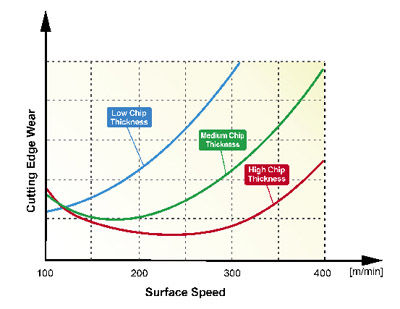
Figure 6—Tool wear as a function of chip thickness and surface speed.
There are certain cutting conditions to consider that basically differ from each other. At the beginning of a non-generated plunge cut, only the blade tips are exposed to a cutting action. As the plunging proceeds, the cutting edges perform more and more chip removal until the end of the plunge cycle, when the chip load is the highest. The tips of the blades are cutting material from the first contact between cutter and part until the end of the cycle. As the tool feeds into the material of the blank, the tip is of course first and will take chips during the entire plunge process. In the case of a 10 mm tooth depth, this means the tip is involved in taking chips for the entire 10 mm. If the cutting section of the blade is 10 mm tall, then the section in the example given that is 9 mm away from the tip (toward the cutter body) will only be in cutting contact the last 10% of the cutting and therefore experience less wear.
The requirement from a cutting cycle is to protect the blade tips from chipping and wear and minimize a blade pressure angle change that is caused by the difference in time that the different sections of the cutting edges have in contact with the slot they cut. The single ramp, shown in Figure 7 (orange graph), is the result of many cutting trials and parameter studies that have been conducted to optimize cutting performance. The proportionally reduced plunge feed rate while the full depth position is being approached (abscissa) leads as a result to a constant or slightly increasing chip load. The third cutting condition is the “dwell” on the end of the cycle.
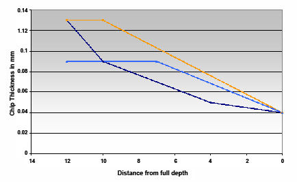
Figure 7—Single ramp for optimal chip load.
In face milling, the cutter has to make one additional revolution at the end of the plunge. This assures that the widest or tallest blade has the possibility to take a last small chip to achieve consistent flank form, from slot to slot and also to reduce the spacing error. The dwell time is calculated to be just 5% longer than required for one revolution. The fact that some blades will take a small chip during the dwell rotation and others may only rub along the flank surface is very negative for the tool life. It is recommended, depending on the face width, to reduce the dwell time to the lowest value that assures that every cutter blade passes one additional time through the slot, after the plunge feed motion comes to a halt.
In face hobbing, the dwell time is calculated as the hunting between cutter and work. If the work has 37 teeth, then the cutter is required to make 37 additional revolutions after reaching the full depth position. This assures that every blade is sent through every slot before the cutter withdraws and the cycle ends. Similar to face milling, the dwell in face hobbing provides better spacing and more consistent flank forms.
Balancing cutting edge wear between inside and outside blades is a very desirable technique to extend the tool life of a cutter head. In many cases, the inside blade experiences significantly more wear than the outside blade, e.g., for the plunge cutting of non-generated ring gears. A very effective plunge cycle modification is the use of a plunge feed vector, which is oriented as profile tangent of the inside flank. The principle of the so-called extreme vector feed is shown is Figure 8. It is possible in cases of high inside blade wear to balance the wear between inside and outside blade, which can in some cases double the tool life.
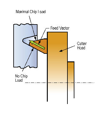
Figure 8—Extreme vector feed.
Optimal Tool Geometry
Angles like side rake and effective hook angle are the primary technological angles that influence the chip formation process. The relief angles like side relief angle and top relief angle are secondary technological angles that have an influence on the wear mechanism only (Fig. 9). The technological angles do not influence the tooth geometry and can be used for the optimization of the cutting process (Ref. 3).
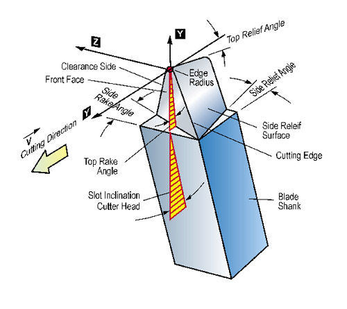
Figure 9—Blade angles and blade nomenclature.
In three-face sharpening, all three blade surfaces that form the cutting edge, the tip and the secondary cutting edge at the clearance side are ground for blade sharpening. Since the coating is removed from all cutting edge forming surfaces, a coating after three-face sharpening is required. In such a case, the advantages due to the freedom of defining all technological angles optimal for every individual job are superimposed with the positive influence of the all-around coating, which will subsequently occur if only the blade shank is masked to avoid multiple layers of coating from changing the blade shank dimensions.
This has to be compared to a two-face sharpening. Here the front face keeps its permanent coating during the entire life of a blade stick. The re-occurring cost of the coating as a consequence of three-face sharpening—as well as the shipping, handling and elapsed time—generate additional costs that have to be justified by higher tool life and a more economical cutting process.
It is possible to optimize all technological blade angles in a three-face sharpening process and then try to match the same blade geometry with permanent, front- face-coated blades. This presents three basically different types of blades:
Blade Type 1—Three-face-sharpened and all-around-coated with optimal angles.
Blade Type 2—Two-face-sharpened, front-face-coated with standard rake and hook angle.
Blade Type 3—Two-face-sharpened, front-face-coated with optimal angles.
The blade hook angle, as shown in Figure 10 in the left diagram, forms a sharp cutting edge around the tip of a blade. For high-speed steel cutting, this was desired. A neutral rake angle for the tip, as shown in the middle diagram of Figure 10, was the limit of an allowable hook angle for high-speed steel cutting. For permanent-coated front faces, the effective hook angle results from the “interaction” of side rake angle and blade pressure angle. This leads to the definition of the cutter head slot hook angle such that, within the variety of expected blade pressure angles, the effective hook never became negative. The slot hook angle is 4.42° in face hobbing cutters and 7.42° in face milling cutters as they are defined for PENTAC® cutters.

Figure 10—Blade hook angles.
For a high-speed carbide cutting environment, the hook angles of high-speed steel cutting appear too high. The hook angle makes the tip of the blades more or less sharp. In the case of high-speed cutting with carbide blades, chips are formed with a high kinetic energy.
Plasticization of steel to form chips with a high content of kinetic energy in the process requires less sharp cutting edges then conventional high-speed steel cutting. A situation between the center and right-side graphic in Figure 10 delivers the best tool life results. The three-face sharpening enables finding an individual optimum for every job.
The side rake angle of 12° in pre-raked blades was based on the experience with high-speed steel cutting. Carbide high-speed cutting requires a lower side rake angle. Here the optimum can be found between Figure 11’s center and bottom sections, depending on workpiece material and job-specific parameters.
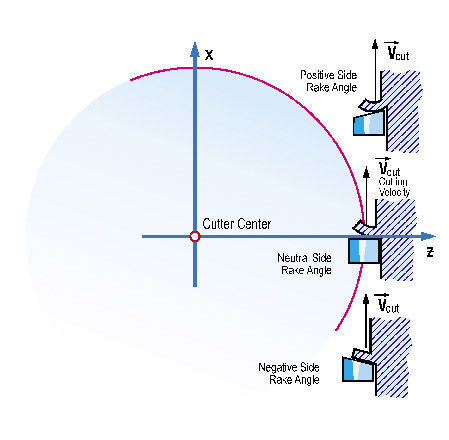
Figure 11—Blade side rake angles.
Most cutting experience with three-face-sharpened blades pinpoints an optimal side rake angle between 3° and 6° and an effective cutting edge hook angle between 0° and 4° (the positive angle corresponds to Figure 10, left-hand side). It is proposed in this article to develop cutter heads with a 4-5°, built-in slot hook angle and to use pre-raked blades with a side rake angle of 4-5° to establish Blade Type 3 as a true alternative to three-face-sharpened blades (Type 1). The pre-raked blade design in Figure 12 can be mounted in a cutter head with a 4° slot hook angle to represent Blade Type 3.
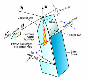
Figure 12—Blade with permanent-coated front face.
A full cost calculation for a representative automotive job delivers about $20 for the refurbishing of one three-face-sharpened blade and $10 for a two-face-sharpened blade.
Those calculations also considered cutter building and re-qualification of the first part. Figure 13 shows that, in cases when the two-face-sharpened blade has only half the tool life of the three-face-sharpened blade, then the tool cost per part breaks even. In case of a “two-face” tool life of only 10% compared to the “three-face” tool life, the tool cost per part of the two-face ground blade is 10 times higher than that of the three-face-ground blade.
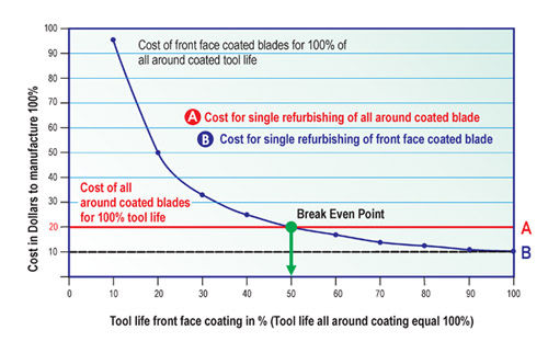
Figure 13—Tool cost per part of all-around-coated and front-face-coated blades.
This estimation seems to be very realistic with respect
to comparisons that have been made in the automotive industry (Ref. 4).
The blade and cutter geometry proposed in this paper was the basis for cutting trials with front-face-coated blades which corresponded to Blade Type 3. The cutting trials showed tool lives that were between 40–60% of the “three-face” tool life.
The conclusion therefore is that the tool costs per part for Blade Type 3 are about identical to the tool costs of Blade Type 2. Blade Type 1 is therefore only advantageous if a specific production environment rewards the avoidance of blade sharpening and cutter building. This also explains why, in many cases of mass production, Blade Type 1 is the preferred choice.
Tool life results from conventional high-speed steel wet cutting, together with results from carbide wet and dry cutting dating back to the early days of Powercutting and the latest cutting results from blades that consisted of Style 1 and Style 3, were compiled to create the graphs in Figure 14. The pull point of the cutter head was defined as the number of parts cut when the wear land on the side relief surface exceeded a width of 0.25 mm. Only the point on the end of the tool life was transferred from the cutting trials to the diagram of Figure 14. The rest of the graph is only of qualitative nature and is not based on measurements.
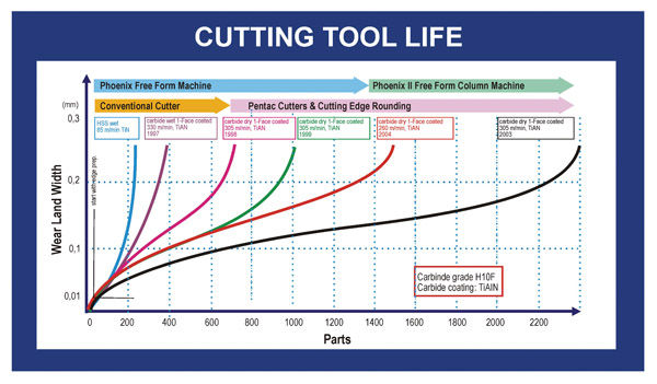
Figure 14—Tool wear as a function of chip thickness and surface speed.
The green graph in Figure 14 corresponds to blades of Type 2 (pre-raked blade with 12° side rake in a cutter head with standard built-in hook angle). The red graph in Figure 14 results from blades of Type 3 (optimized 4° side rake angle in a prototype cutter head with 4° built-in hook angle). State-of-the-art cutting with three-face-sharpened and all-around-coated blades (Blade Type 1) resulted in the black graph in Figure 14. All graphs in Figure 14 are based on
cutting results of automotive size ring gears.
Increase of Blade Point
The tips of the blades are rather sensitive parts of cutting blades. A relatively small volume of carbide material forms a considerable portion of the blade cutting edge. During a plunge cutting process of a gear, the blade tips are in contact with the workpiece material during 100% of the cutting time. The cutting edge length between the reference point and the end of a blade edge is only in contact with the work piece about 50% of the cutting time. In other words, the small blade tip area has the most cutting contact of the entire cutting edge. This also shows some potential area of improvement if it is possible to increase the ratio of (carbide volume) / (removed chip length) e.g., by increasing the blade point.
The difference between point width and blade point (Fig. 15) is the clearance between the clearance side blade edge and the material of the slot that was cut by the opposite blade (Fig. 16). To avoid chip dragging and scuffed or scratched surfaces as well as possible contact of the clearance side blade edge with the workpiece material in the slot, the clearance value needs to be 0.3 mm or larger. Subtracting a value of 0.3 mm or more from the point width delivers therefore the blade point. Optimal tool life can be expected only when a blade point is above 0.8 mm. If a blade point is below 0.8 mm, it is recommended to change the basic geometry of the job or the split between gear and pinion blade point in case only one of the two exceeds the critical width of 0.8 mm.
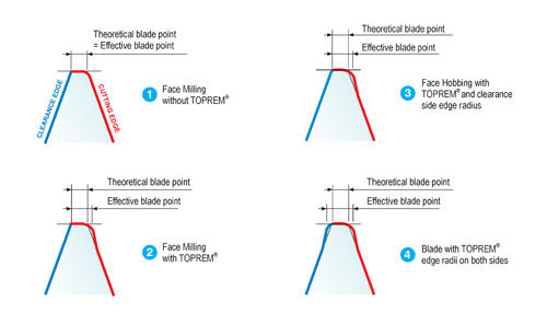
Figure 15—Artificial increase of blade point.
Besides an unacceptable tool life, the small blade point will not allow a large enough edge radius in order to form an optimal strength root fillet. This also leads to a degradation of the fillet radii as well as a degradation of the surface roughness in the root.
An “artificial” increase of the blade point width is possible if protuberance (TOPREM®) is used on the cutting edge and on the clearance side blade edge. The cutting edges in a face hobbing process should prepare the flank surface for the final lapping. Also, for the face-hobbed gears, a small amount of protuberance is recommended for optimized, modern developments. In most cases, when the cutting is conducted in face milling, the following hard finishing
operation is grinding (which makes the soft cutting a semi-finishing process). Semi-finishing operations of pinions and gears have to be performed with blades that include an amount of protuberance that relieves at least 50% of the stock allowance in the root area. In all cases of face hobbing and face milling, protuberance zones in the blades are recommended if a material-removing hard finishing operation follows the heat treatment. This in turn justifies the application of protuberance in the blade clearance side edges. The rule is to use on the clearance side of every blade style the exact same amount of protuberance (angle and depth) that is used on the cutting edge of the opposite member (OB IB) to achieve an equidistant clearance along the entire depth of the blade clearance side and yet get the largest possible effective blade point (see Figure 15, steps 1 to 4).
Another possibility to increase the blade point is called the “full point width blade system.” The blade tip geometry of this system fills out the entire reference profile. A schematic example of an inside and an outside blade is shown in Figure 16. This system was not only developed to achieve the largest possible blade point, but it realizes the idea of additional cutting action and better utilization of the blade tip region, which in most cases defined the end of a tool life because of its excessive wear. Figure 16 shows that the inside blade has cutting contact on the inside cutting edge, the inside edge radius, the flat tip region and along the entire clearance side radius, which is now also part of the active cutting process. The compound angle between side rake and hook (see also Figure 9) will provide the optimal angles only for the primary edge radius on the cutting side. The clearance side radius has the identical hook angle but is left with a non-optimal negative side rake angle. This negative side rake angle has no influence on the end chips at the bottom of the slot. The influence of the negative side rake angle is the largest where the radius begins to back away from the material to provide the chip clearance. If the full point width clearance radius is designed such that it starts to back away from the clearance side root radius at the root bottom (which is basically produced by the cutting edge radius of the opposite blade), then this newly created semi-active part of the blade works as a roughing section that prepares the clearance side root for the finishing action of the following blade. The “full point width blade system” can achieve a determined roughing-finishing split between the radii of the opposite blades. It can achieve a tremendous increase of tool life because of the consolidation of three positive effects:
• Maximum blade point for rugged and durable blade tip.
• True roughing and finishing action in tool-life-limit ing blade region.
• Consistently high root surface finish (often used as cutter pull criterion).
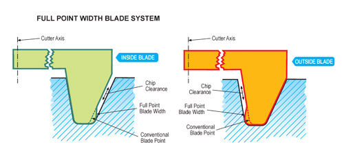
Figure 16—Full-point-width blades.
Typical Blade Wear
The typical “healthy” wear pattern of carbide blades is a wear land on the side relief surface as shown in Figure 17, bottom left. The small chip crater on the cutting edge did not lead to an early failure of the blade. Figure 17 shows different blades at the end of their tool life. The upper-left photo shows an abrasive wear on the front face. The upper-right photo shows abrasive wear on the top relief at the tip and a chip on the cutting edge, which most likely was caused by the blade handling. The discoloration around the cutting edge is mostly due to the abrasive removal of the decorative top layer of the coating.
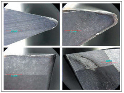
Figure 17—Different face coated blades at the end of tool life.
The lower-right photo in Figure 17 shows a clearance side relief surface with chip scratches. This indicates that the side relief angle is too small and/or the chip clearance (see Figure 16) is not large enough. The lower two photographs in Figure 17 also show the separation of the relief surfaces in primary and secondary land. The primary land is between 1 and 2 mm wide and represents the finishing surface. The secondary land extends over the remaining side relief with a larger relief angle. The secondary land is rough ground only. It is particularly recommended to split the side relief surfaces in primary and secondary lands.
Figure 18 shows two blades at the left side with cutting-edge chipping, which could be caused by unacceptable cutting vibrations or initial micro chipping after blade sharpening and insufficient edge rounding. A blade with cratering wear is shown at the right side of Figure 18. This wear could be caused by insufficient coating protection or too high cutting surface speed.
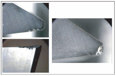
Figure 18—Blade chipping and cratering wear.
Figure 19 shows some blades that failed due to abrasive side relief wear, which can be caused by too high cutting surface speed and too low side relief angle.
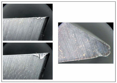
Figure 19—Abrasive wear on side relief surfaces.
Optimal Refurbishing of Carbide Blades
The blade photos in Figure 20 show a grinding result of permanent front-face-coated blades. The surface finish of the cutting edge side relief is high and the transitions between cutting edge and edge radius are smooth. The clearance side edge radius is very small, which is not considered optimal. Surface roughness or waviness in a clearance side relief surface, as shown in the right-side photo of Figure 20, is acceptable.
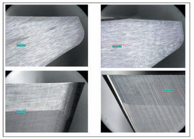
Figure 20—Carbide blades after sharpening.
To achieve optimal cutting conditions and good tool life, a number of rules have been established that can be used to judge and improve the blade-sharpening process.
• Split side relief surface in primary and secondary land.
• Primary side relief between 10 and 16°.
• Side relief angle of secondary relief surface 6°.
• Grinding direction from cutting edge into side relief.
• High surface finish without waviness (Rz = 0.4– 0.6µm).
• Transitions between edge radius, protuberance and cut ting edge very smooth.
• Use roughing and finishing cycle for better transitions, higher accuracy, better surface finish and lesser risk of thermal damage.
• Sufficient grinding depth to remove destroyed carbide structure below the surface (0.3–0.8mm in shaft direc tion).
• Use grinding oils that prevent cobalt leaching.
• Avoid thermal damage.
• Possibly demagnetize blades after sharpening.
• Cutting edge rounding 5–10 µm for Blade Type 2 and 3.
• Use lowest possible blade stick out in cutter head.
References:
1.Maiuri, T.J. “Spiral Bevel and Hypoid Cutting Technology Update,” AGMA Fall Technical Meeting, October 2005.
2.Stadtfeld, H.J. “Advanced Bevel Gear Technology, Manufacturing, Inspection and Optimization,” Gleason publication, May 2000.
3.Stadtfeld, H.J. “The Two-Sided Ground Bevel Cutting Tool,” Gear Technology magazine, May/June 2003.
4.Stadtfeld, H.J. “Optimal Parameter for Bevel Gear Cutting Innovations in Bevel Gears,” WZL Forum Aachen, March 2004.
Hermann J. Stadtfeld is vice president of bevel gear technology at Gleason Corp. He received a doctoral degree from Technical University of Aachen (WZL) in 1987 and taught bevel gear design at Rochester Institute of Technology and at Technical University Ilmenau, Germany. From 1991-2002, Stedtfeld was vice pesident of research and development at Gleason. He was authored more than 15 books and 130 papers on bevel gearing and has received more than 30 patents related to gearing.
This article is an updated version of a paper published by thAmerican Gear Manufacturers Association. It is presented with the permission of the copyright holder. Statements
presented in this paper are those of the author and may not represent the position of the AGMA.


