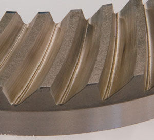
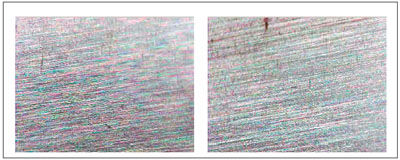
A finish-ground bevel gear set should have an Rz equal to or less than 5 µm and an Ra equal to or less than 0.8 µm.
The ground surfaces of hypoid gears always carry the risk of scoring during the initial wear-in period. To eliminate this risk, the flank surfaces of at least the ring gear should be phosphated. The risk of scoring may also be eliminated during the first operating period through the use of synthetic hypoid oil. Nevertheless, the risk of scoring in operation is reduced due to the enhancement of the surface finish.
Keys to efficient grinding are the abrasive material and the abrasive bond. Recommended for bevel gear grinding are grinding wheels with an abrasive of sintered aluminum oxide with an 80 grit and a soft ceramic bond with an open pore structure.
Three or four coolant pipes are directed tangentially to the grinding wheel circumference with a coolant speed about equal to the grinding wheel surface speed to apply a layer of coolant to the grinding profile surface just before its entrance into the grinding zone. Additional pipes are located behind the grinding zone and are directed opposite to the grinding speed to extinguish the sparks, which would burn into the wheel bond and get into the grinding zone.

In addition, the wheel’s surface has to be cleaned continuously with a high-pressure coolant jet that’s connected to an extra pump, supplying the coolant at a pressure of at least 300 psi. The high-pressure jet has to be located about opposite the grinding zone and has to shoot coolant perpendicular to the profile surface. Because of centrifugal force, the chips tend to clog up the inside profile more, so appropriate attention must be paid to the design and function of the
high-pressure cleaning system. The surface speed to achieve good surface finish in connection with minimal grinding wheel wear is 20-24 m/sec, a rather low value for a grinding process.
In the automotive industry, bevel gear grinding requires one rotation only, but each slot may be ground in two passes--the so-called double roll. This roll consists of one pre-finishing pass, during which the grinding machine moves the grinding contact from toe to heel (uproll) and one fine-finishing pass, rolling from the heel back to the toe. While a part is being ground, dressing should be done after a rotation is finished, not during the rotation.
In contrast, some gears for high quality machine tools require two rotations, and aircraft parts are ground in four or more rotations.
In all cases, though, the rule is: After each rotation, the grinding wheel should be redressed.
However, skip indexing should be avoided. This technique was developed in order to distribute wear more uniformly around the work, to avoid ramp-shaped spacing errors. Rather than grinding successive slots, skip indexing skips a preset number of slots. Consequently, grinding requires several revolutions to finish all slots.
Subsequently, though, it was discovered that many acoustic phenomena were caused by skip indexing. Experience with the technique showed that the resulting many small ramps generate noise
with amplitudes in the tooth mesh frequency, the gear rotational frequency and with a frequency that corresponds to the number of ramps per revolution. In some cases, there even appears to be an additional modulation. Thus, wear compensation is the best way to reduce ramp-shaped spacing errors and other wear patterns.
Dressing the grinding wheel requires a dress roller that is diamond-plated and shapes a grinding wheel’s profile like in a round grinding operation. But the wheel must not be dressed with a dress roller using single-point dressing. This is the type of dressing in which the dressing wheel is locked during dressing, so the relative surface speed comes only from the rotation of the grinding wheel (speed ratio: 0). Consequently, single-point dressing creates a flat spot on the wheel. Dress rollers, however, are designed to dress around wheel circumferences.
The wheel also must not be dressed when the roller’s surface speed is equal to the wheel’s surface speed (speed ratio: 1.0). At that ratio, the roller crushes the abrasive grain out of the wheel bond.
The crushing breaks complete grains out of the bond for the most open-pore wheel surface structure possible. The grinding improves the wheel’s ability to grind gears, though it also reduces the structure’s pore size. However, the combination of crushing and grinding is optimal.
The grinding between dress roller and grinding wheel surface reduces pore size by changing the remaining crystal-shaped grains, specifically by flattening their sharp corners, the ones towards the surface. Consequently, very small flats are generated.
This flattening is beneficial because the grains’ original shape is only good for roughing, not finishing. Their crystal shape can’t accurately represent the grinding wheel’s dimensions and profile shape. Consequently, the surface roughness of ground gears will be high and not very accurate.
The very small flats can, however, accurately represent the wheel’s diameter and profile shape. The changed crystals mean surface roughness of ground gears will be low, coolant will be able to access the grinding zone and removed material will be able to move out of the grinding zone.
For high-productive grinding, a dresser speed ratio of 0.6-0.8 is recommended.
For the highest possible surface finish, the recommended speed ratio is between -0.6 and -0.8. In that ratio range, the roller only shapes the abrasive grains--it doesn’t crush them--and results in a grinding wheel surface with minimum pores. Grinding wheels can be dressed for this type of grinding by directing the roller speed against the grinding wheel speed, which leads to high relative velocities.
Gear manufacturers can also remove the grinding wheel’s wear pattern from the gear finish by entering into the grinding machine’s controller the number of teeth for fast wear and the percentage of this wear from the entire amount of wheel wear.

Wheel wear occurs rapidly during the first couple of slots and then with near-linearity for the following slots. Modern grinding machine controls have wheel wear compensation features that allow total wear compensation for the entire part and a fast wear compensation for the first slots. After total wear is compensated, the spacing measurement will show whether the first slots require additional compensation and whether that amount should also be removed from the remaining slots.
After grinding a number of development gears, a manufacturer can obtain the numbers needed for eliminating the wheel wear pattern--specifically, the amount of fast wear on the wheel, the number of teeth for this fast wear and the entire amount of wheel wear.
When finishing Formate(TM) ring gears, they should be ground using Waguri grinding to make the process more stable and faster.
Normally, Formate gears are ground in a plunge-cut cycle. In form grinding, that means the grinding wheel has simultaneous contact with the whole flank surface of both flanks of a slot. Coolant can’t reach the grinding zones, with the results being burning and fast grinding wheel contamination with metal particles.
The process can be made stable, however, through a different, additional rotation of the rotating grinding wheel spindle. This other rotation should be about 0.3 mm eccentric in the plane of rotation about the theoretical grinding wheel axis. The eccentric rotation’s speed should be 200-500 rpm lower than the grinding wheel speed, with a typical value of 2,000 rpm and the same hand of rotation as the grinding wheel itself. This grinding technique is called Waguri,
after its inventor.
Waguri grinding is extremely fast. It can achieve grinding times of one second per slot. A Waguri ground gear with 35 teeth is ground more quickly than a conventionally ground pinion with 13 teeth.
Lapping both finishes a gear and pinion and mates them together. Grinding doesn’t. This seeming deficiency can be an advantage for gear manufacturers. When finished via lapping, the mated gear and pinion must be kept together. When finished by grinding, gears and pinions can still be dealt with individually. Their mating can be delayed until assembly.
Before assembly, a gear and pinion can then undergo roll testing to determine their axial pinion shim value. Afterward, they must be labeled with the value and kept together. They are, in effect, mated via roll testing.
By being able to delay mating, gear manufacturers that grind have less complicated logistics and more flexible manufacturing than those that lap.
Also, each gear set should undergo roll tests for three or five different axial pinion positions. These tests are recommended because they often reveal a best pinion axial assembly position.
Moreover, roll testing should be combined with a structure-borne noise evaluation. The noise test isn’t as important, though, for ground gear sets in transaxle or power takeoff units because noise is not an extremely critical issue for them.

Lastly, don’t be tempted to favor lapping over grinding for economic reasons. Admittedly, grinding is slower and more expensive than lapping. For example, grinding a pair of bevel gears requires two grinding machines and two minutes for each gear. Lapping also takes two minutes for each gear, but it requires only one lapping machine. Moreover, the grinding machine cost per ground set is about three times the lapping machine cost per lapped set.
However, rejected parts and customer complaints are 1% or less for typical grinding production compared with 3-7% for lapping, depending on the requirements for certain jobs. Rejected gear
sets include the cost of all previous operations plus the material. Consequently, the cost related to this difference in reject rate often makes grinding the more economical process.
Lapping remains competitive, though. Many United States bevel gear manufacturers use it rather than grinding, having selected it when grinding was still developing into a reliable finishing process for higher-volume gear production. Today, a split even exists between U.S. and European bevel gear manufacturers over lapping versus grinding. The split is discussed in a related article.
The above guidelines have covered topics from grinding wheels’ abrasive bond to the transition line between root and flank of face-milled gears, but this list isn’t all-encompassing. A major reason so many unwritten guidelines are unwritten is because they’re infinite in number and change with advances in materials, processes and equipment. Still, these guidelines should help gear engineers to skillfully grind their bevel gears.
Dr. Hermann J. Stadtfeld is managing director and co-founder of BGI GmbH &
Co KG. Located in Eisenach, Germany, the company specializes in development and
application of bevel gears for the automotive industry. Before BGI, Stadtfeld was
a vice president and head of research & development for Gleason Corp. Effective
Dec. 1, he will return to Gleason as its vice president--bevel gear technology. Previously,
he’s also served as director of engineering and research with Oerlikon GearTec AG in Zürich, Switzerland. His technical education began with an apprenticeship at ZF Friedrichshafen AG, a major European gear manufacturer. In addition, he received his doctorate in mechanical engineering from the Technical University of Aachen, Germany, researching bevel gears for
his dissertation. Stadtfeld has spent more than 20 years developing software, hardware and other processes for gear design and optimization. He also trains engineering students at universities and gear engineers in companies around the world.
For more information:
BGI GmbH &Co KG
Rennbahn 25
D-99817 Eisenach
Germany
Phone: +(49) 3691-684-386
Fax: +(49) 3691-684-374
office@bgi-auto.com
www.bgi-auto.com


