Figure 4 shows the sliding and rolling velocities of a spiral bevel gear. The velocity directions are based on the sliding and rolling of the gear flank versus the pinion flank. While the rolling velocities have only moderate changing magnitudes in the entire flank area, the sliding velocities reduce their magnitude from the root line to the pitch line and become zero at the pitch line. At the pitch line, the sliding velocities change their direction and increase in magnitude as they get closer to the tip.
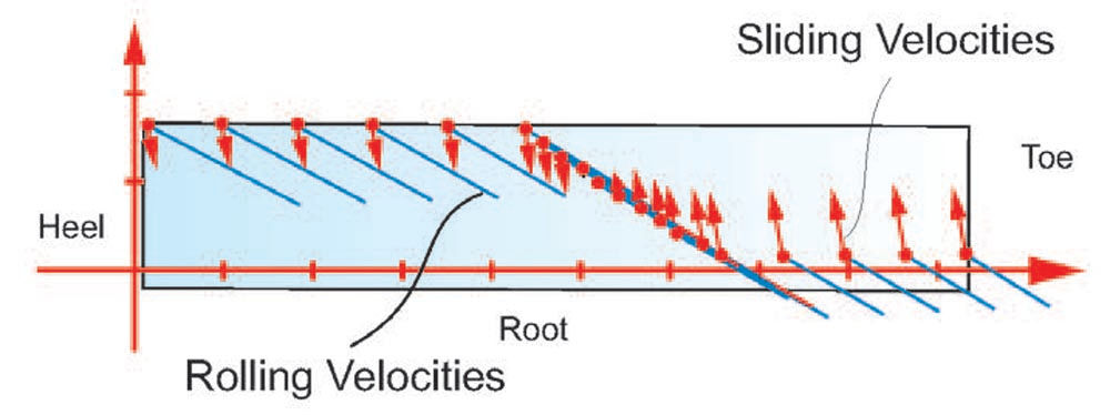
Figure 4—Sliding and rolling velocities along the path of contact of a spiral bevel gear.
If driving on the drive side as explained in Figure 3 is realized, the sliding and rolling velocities are still of the same magnitude but in the opposite direction as it would be in the case of a speed reducer. Positive pinion profile shift or addendum modification will increase the diameter of the pinion root and face, and therefore position the pitch line (which cannot be moved) close to the flank transition to the root fillet. This will cause the lowest sliding velocities at the pinion root transition. However, in turn, the largest sliding velocities are now at the pinion tip and the gear root. Because speed increasers are prone to scuffing at the pinion and gear root, it is recommended to avoid profile shift to achieve balanced conditions between both meshing members.
To further reduce the risk of scuffing and the risk of lubrication deficiencies, the applied lubrication concept is most important. The optimal orientation of a speed-increasing gearbox is such that the gear has a horizontal axis and is about 50 percent below the oil level, while the pinion just dips below the oil level. This orientation will keep oil churning at the lowest possible level and forced lubrication is not required. The basic rule is to keep the low-speed member about 50 percent below the oil and ensure that the high-speed member just contacts the oil, such that after long periods of not operating the gearbox, the pinion is not dried off on all of its teeth.
Recommended oil types are high-pressure fully synthetic oil, as used in hypoid axles of premium class vehicles (for example Castrol SAF-XO). These synthetic oils have low viscosity and provide high pressure and scuffing-prevention properties which are beneficial for speed-increasing transmissions.
Figure 5 shows a severe case of scuffing in the high sliding area (dedendum) of a hypoid gear. The gear in Figure 5 was mating with a pinion which had a too large profile shift, which made the gear dedendum large. The large distance from the pitch line caused high sliding velocities along the flank-root transition which initiated the scuffing. As mentioned in the last section, a zero profile shift in the driven pinion is advisable. The risk of scoring of hypoid gears is always larger than in the case of spiral bevel gears, which comes from the additional sliding in the face width direction, in a magnitude that is nearly proportional to the hypoid offset and larger than the profile sliding.
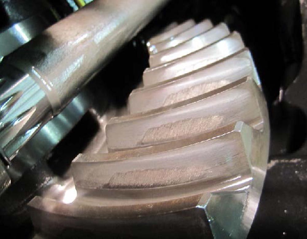
Figure 5—Scuffing in the root area of a hypoid pinion without profile shift.
Starting with Full Output Load
The forces on the contacting flank surfaces are identical between speed increasers and speed reducers. Figure 6 shows the simplified representation of the flank and bearing forces. In both operating directions (speed reduction or speed increase) the force diagram in Figure 6 applies equally. During the startup of a transmission, it is important to consider if the load is applied with a smooth ramp-up or if the transmission has to work against full load from the start. Speed increasers may work in a steady-state operation, however, during the startup, the acceleration of the output gear, turning faster than the input gear, increases the torque versus the steady-state torque. This effect is no issue in a speed-reducing transmission, but it requires designing the gearset for a higher output torque in the case of speed increasers. The load exaltation factors (LEF) in Table 1 are proposed to account for the additional inertia torque during the acceleration from zero to nominal RPM. The factor LEF has to be multiplied by the overload factor found in AGMA 2101 or the application factor found in ISO 6336 or DIN 3990 (Ref. 6).
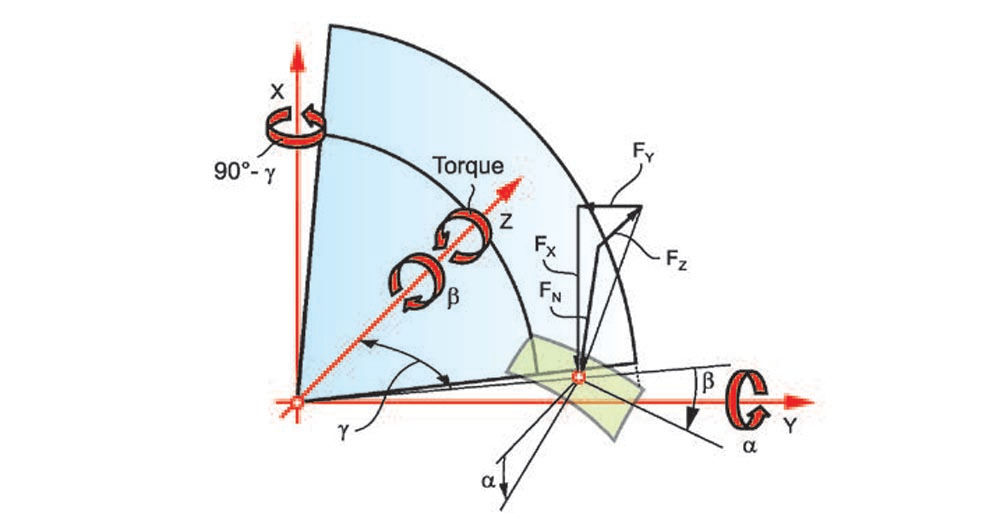
Figure 6—Flank contact forces and bearing forces.
Depending on a smooth load increase proportional to the RPM ramp-up, or an instant full load condition with an abrupt input speed increase, two categories are listed in Table 1. The table also differentiates between ratios of one to four. In case of ratios higher than four, the values in Table 1 for the ratio 4:1 can be used. Most real applications have a startup characteristic between proportional and full-load startup. It is up to the gear engineer to estimate the LEF that applies to the input/output conditions of a particular gearbox.

Table 1—Load exaltation factor.
Dynamic Effects
One dominant effect of a bevel gear speed increaser is the increase of the motion error amplitude of the output gear. This is caused by the flank surface crowning, which is significantly larger in bevel gears compared to cylindrical gears. The same gear set was first applied as a speed reducer with the pinion driving the gear. It shows a motion error amplitude of A1 of the output gear in Figure 7 (top graphic). Then, the gearset was used as a speed increaser with the gear driving the pinion, which resulted in a motion error amplitude of A2 of the output pinion, shown in the bottom graphic of Figure 7. Caution has to be applied during the design because this effect is not seen in a common TCA which bases all results on the ring gear. The ratio of the gearset in Figure 7 was 17:45 (R = 2.64). Reversing the driving direction increased the motion error by the exact factor of 2.64 of the ratio.
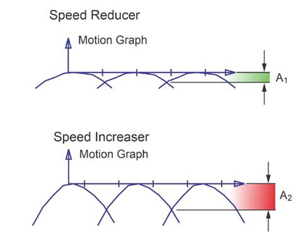
Figure 7—Motion error increase due to speed-increasing arrangement.
The output pinion in a speed increaser has a motion error amplitude that is larger by the factor of the ratio compared to a speed reducer. This presents in many cases a severe problem in the performance of the transmission. The first derivative of the motion error Δφ in Figure 8 is the angular velocity Δω. The graphic shows that, against the common opinion, the gearset slows down along the entire motion error graph. Only at the transfer point between the actual pair of teeth to the following pair does the angular velocity (RPM) increase to the level at the starting point very instantly. This abrupt speed increase is called the meshing impact. To quantify the impact, the second derivative of the motion graph is made which results in the angular acceleration Δα. The amplitude of the peak in the acceleration graph will be 2.64 times higher in the case of a speed increaser, versus a speed reducer. In the case of large inertia on the output side of the speed increaser, the higher acceleration peak will be smoothed out and less disturbing. However, the exaggerated impulse will increase the load that the teeth of both members (pinion and gear) are experiencing.
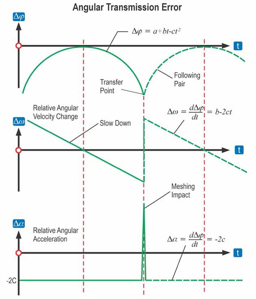
Figure 8—Impulse caused by motion error (angular transmission variation).
In the case of a low inertia on the output side of the gearset, vibrations with the tooth mesh frequency will be experienced. These vibrations can result in flank separation during the slow down period (along the drop of the Δω velocity graph) because the deceleration Δα of the speed increaser is elevated by the factor of the ratio Δα = R . (-2C). Flank separation will not only cause a hammering sound but will also result in a lubrication film interruption at the transfer point when the impulse occurs. Reducing the motion error in the design calculation will reduce the flank separation effect and applying the dynamic load factor DLF will account for the higher average contact forces.
A lubrication film interruption cannot be compensated in the design calculation of the gearset in the case of a higher output inertia. Because the flank separation is more likely with ratios greater than 2, it is required to design the Ease-Off of a gear set with a ratio larger than 2 nearly conjugate and account for the prevention of edge contact in case of deflections and component tolerances, by applying blended Toprem and kinematic heel relief.
Recommended dynamic load factors DLF are listed in Table 2. For low output inertia, the factors in the left column are a guide for the design of a gearset. The DLF factors have to be multiplied with the nominal load of the particular application (in addition to the dynamic factors from the standards or the literature [Ref. 7]) when strength calculations are performed. For high output inertia and ratios above 2, an increase in the strength of the speed increaser will not help to account for the separation, the flank hammering, and the interruption of the oil film. A good guide is to reduce the motion error by the factor of the ratio. Ideal in this case are motion errors in below 15 microradians. Low motion errors require nearly conjugate flank surfaces with very low Ease-Off magnitudes. Because the Ease-Off accounts for deflections, heat-affected deformations, and manufacturing tolerances, a conjugate Ease-Off will result in edge contact in the operation of the gearset. To re-establish the required insensitivity of the gearset and prevent edge contact, the conjugate design requires blended Toprem in the pinion and gear member as well as a kinematic heel relief. Because speed increasers for power transmissions should be ground, Toprem and end relief are easy to realize and are standard features of bevel gear grinding machines.

Table 2—Dynamic load factor accounts for motion error elevation.
Maximal Ratios and Self Locking
High-reduction hypoids, such as HRH and SRH have a tapered worm as a pinion (Figure 9). The common ratios of these transmissions are between 7 and 50, however, larger ratios are possible. The lowest number of pinion teeth is one, which will result in a very low pinion lead angle.
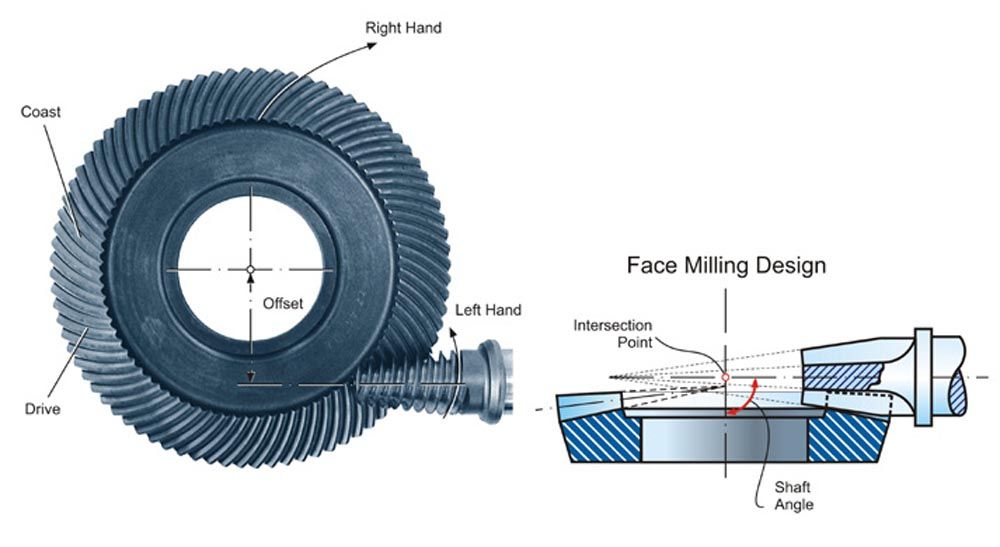
Figure 9—Super reduction hypoid (SRH) used as a speed increaser.
Gleason developed the calculation of a backdriving coefficient (CBD = Tbr/Tdr), especially for SRH gearsets. This calculation is based on a friction factor of μ = 0.08 and computes the torque that tries to backdrive the pinion versus the breaking torque. If CBD > 1, then backdriving is not possible. The backdriving ability of SRH gearsets is important for all applications that require smooth coasting if the driving torque from the prime mover is reduced or turned off.
The lead angle of a 5-tooth and a 2-tooth pinion are compared in Figure 10. A worm with a lead angle of less than 10 degrees is considered self-locking (Ref. 8). Self-locking means the gear cannot drive the pinion. This is a general statement and must be verified, considering the type of lubrication, the lead curvature of the gear teeth, and if the backdriving occurs on the drive side (if the gear in Figure 9 rotates counterclockwise) or if the backdriving occurs on the coast side.
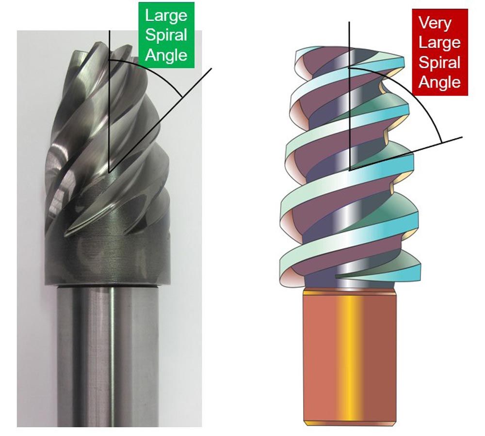
Figure 10—Bevel worm pinion with large lead angle (left) and low lead angle (right).
It is advisable not to use high-reduction bevel worm gear drives as speed increasers. The efficiency of such a transmission when used as a speed increaser is considerably lower than in the case when it is used as a speed reducer.
Bidirectional Operation
If a speed increaser is used bidirectionally, then it has to transmit the same torque on the drive side and the coast side. The effect of coast-side driving like the aforementioned reduction of backlash down to zero has to be reduced (Figure 6 with reversed force directions). One solution is the use of straight bevel gears. Straight bevel gears can be designed and manufactured today with low motion error and acceptable contact ratio. Also grinding of modern Coniflex Pro straight bevel gears is applied today for many industrial applications. If spiral bevel gears are used as bidirectional speed increasers, then a reduced spiral angle and a large cutter diameter should be used. The recommendations for speed reducers in textbooks and design manuals call for a 35° spiral angle and a cutter diameter which puts the involute point at the outer diameter. This is called the ratio of involute to outer cone. In the case of a bidirectional speed-increaser, the spiral angle should not exceed 20 degrees and the cutter diameter should be chosen close to the gear mean diameter. This means, if the mean gear diameter is 190 mm, then the cutter diameter should be 7.5 in. The involute to outer cone rule was established to achieve a favorable contact movement under load-affected deflections on the drive side. In case of a low spiral angle of 20 degrees, and driving on both the drive and coast side, the rules of the involute to outer cone would result in a very small cutter diameter, which is not recommended for speed-increasing transmissions.
Manufacturing and Operation
Either straight bevel gears or spiral bevel gears are recommended as speed increasers. For straight bevel gears, the Coniflex Pro design software and the Coniflex cutting process provide the optimal geometry and optimization features, like conjugate flanks with kinematic tip relief. For spiral bevel gears, the Gleason face milling completing design offers kinematic flank optimizations (UMC) for conjugate profiles and end relief.
It is recommended to case carburize pinion and gear and heat and quench the pinions to a surface hardness of 62 HRC and the gears to 59 HRC. The difference in surface hardness reduces the metallurgic affinity of the contacting surfaces and therefore reduces the risk of scuffing.
After heat treatment, the speed increaser gears should be ground with a low surface roughness, preferably below 0.5 nm Ra. If a controlled break-in with moderate loads and speeds that increase from low to high is not possible, then a superfinishing or phosphate coating of the flank surfaces is recommended.
Hypoid gears which are used as speed increasers should receive a small root relief of 10 to 15 microns in the grinding process. This will prevent load concentration peaks, leading to scoring. After heat treatment, a phosphate coating of the flank surfaces will reduce or prevent flank surface damage.
All speed increasers should be lubricated with fully synthetic high-pressure oil, for example, Castrol SAF-XO. A speed-increasing bevel gear transmission should be filled with 40 to 50 percent of its inside volume with oil. The fast-running pinion has to be placed above the oil level, or just slightly dipping into the oil. If the gearbox is used unidirectional, then an orientation like in Figure 3, with a counterclockwise rotating gear will transport the oil from the sump directly to the pinion teeth. The described arrangement will reduce oil churning. Excessive oil churning reduces the cooling effect the oil should provide, and it reduces the ability for a hydrodynamic oil film between the meshing flanks because the churned oil foam delivers mostly air between the meshing flank surfaces.
If the described ideal condition for an oil sump is not given for a certain design, then a piping system for forced lubrication which pumps low quantities of oil into the meshing zone must be considered. The oil must be supplied before the mesh which means, referring to Figure 3 (gear rotates counterclockwise), the oil supply comes from below. In the case of a bidirectional speed increaser, the oil supply must come from both directions into the meshing zone (above and below in Figure 3).
Summary
Speed-increasing bevel bear transmissions are used in many applications successfully. To create a new speed increaser, the following guidelines and rules of thumb should be considered:
- Meshing on the drive side is important.
- Spiral angle not larger than 27 degrees (single directional on drive side).
- Spiral angle not larger than 20 degrees (bidirectional).
- Avoid profile shift as it improves the sliding condition on one member and worsens the sliding condition on the second member.
- Torque increase during start-up (acceleration because output is faster than input) can be considered with LEF factor in Table 2.
- Motion error increase by speed-increasing arrangement is not seen in TCA and leads to flank separation in the case of high output inertia.
- Low output inertia and ratios below 1:3, reduce profile crowning and apply factor DLF.
- High output inertia and ratios above 1:3 require nearly conjugate Ease-Off and apply blended Toprem and heel relief.
- Avoid worm-shaped pinions with less than 5 teeth.
- If high-reduction gearsets with worm-shaped pinions are used, apply the recommendations mentioned with hypoids and use the largest number of pinion teeth possible in the respective design.
- Ground bevel gears should be used as speed increasers.
- Surface hardness of pinion 62 HRC and Gear 59 HRC (or similar).
- Superfinished flank surfaces are mostly an advantage.
- Phosphate-coated surfaces are always an advantage, especially for hypoids.
- Use oil filling or forced lubrication as recommended above.
- Fully synthetic high-pressure oil reduced the risk of scuffing.
References
- Bra, A. et al; “General aspects of speed increaser gearboxes,” IOP Conference on Applied Sciences 2017.
- Gasparini, G. et al; “The “035” Main Gear Box: Strong, Light, Reliable and Silent Heart of the AW139 Helicopter”, AGUSTA Westland Italy, a FINMECCANICA Company, Cascina Costa, Italy, June 2005.
- Principato, C.; “Power Take Off’s on Helicopter Main Rotor Drives,” KISSsoft AG, Engineering Report, Bubikon, Switzerland, April 2024.
- Yilmaz, C.; “Hypoid Gear Power Transfer Case,” KISSsoft AG, Engineering Report, Bubikon, Switzerland, April 2024.
- Stadtfeld, H.J.; Gleason Bevel Gear Technology—The science of Gear Engineering and Modern Manufacturing Methods for Angular Transmissions, Company Publication, The Gleason Works, Rochester, New York, March 2014.
- Hein, M.; “Ask the Expert—Determining Value of Ka in regard to DIN 3990 and AGMA standards,” Gear Technology, May 2019.
- Raghuraman, N. et al; “Prediction of Dynamic Factors for Helical Gears in a High-Speed Multibody Gearbox System,” Gear Technology, May 2018.
- Rj Link; “Using a Speed Reducer as a Speed Increaser,” RJ Link International, Rockford, IL, Article in www.rjlink.com, April 2024.


