Due to the tight tolerances and the noise sensitivity of transmission components, hard finishing by grinding or honing is indispensable. Gear honing proves to be particularly advantageous since honed surfaces have proven to result in lower noise behavior than ground surfaces due to their specific, curved surface structure. Gear honing is also well suited for the hard finishing of gears with interfering contours, as is the case with the smaller gear on stepped pinions.
This is due to the small necessary cross-axis angle between the honing tool and the component and the fact that no tool overrun paths are required, as is the case, for example, with grinding. Hence, honing is the mandatory process to finish the smaller gear, whereas the larger gear could also be ground. However, this would require the application of two different processes, bringing with it several disadvantages. Not only would two different machines with different clamping fixtures and tools be required, but the process control would also be extremely challenging, especially to achieve a very tight timing tolerance between both gears. Using two different machines also doubles the unproductive idle time required for loading and unloading as well as for indexing both gears.
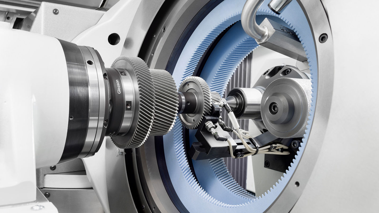
Gleason’s Combi Honing process can eliminate these disadvantages. Combi Honing offers the possibility of using two honing rings in parallel within the honing head of a 260HMS Honing machine, hence delivering an ideal solution for honing both gears of the synchronized stepped pinions in one clamping (Figure 3).
Figure 3—Combi Honing on a 260HMS Honing machine.
As simple as the idea may seem, there are still important details to consider. If only one honing ring is used, its working point will always match with the swivel point of the honing head (A-Axis). Instead, if two honing rings are used—as in the case with Combi Honing—at least one honing ring will not be in the swivel center point as shown in Figure 4. This situation results in an offset of the actual operating point in Y-direction which, if not compensated for, will cause tapered gears, clearly visible as flank line deviations (fHresignb deviations on the left and right flank).
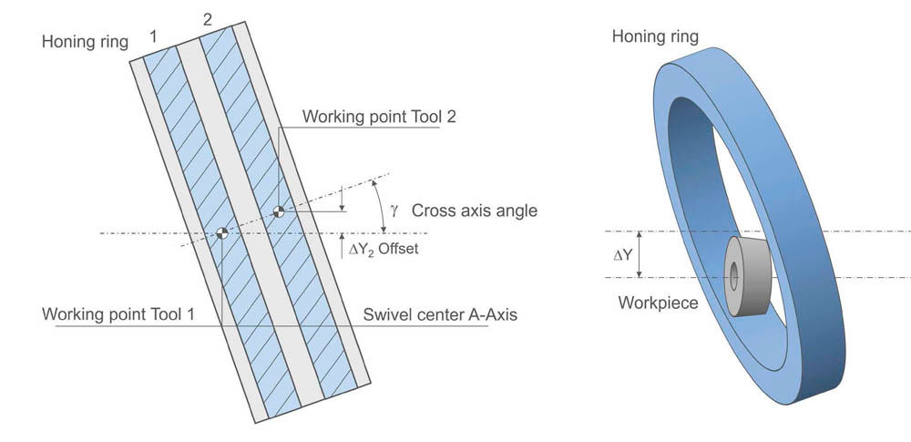
Figure 4—Offset in Combi Honing.
To compensate for this unwanted effect, Gleason honing machines are equipped with an additional B-axis (swivel axis), which is also used to influence flank line modifications such as crowning and desired lead deviations.
The Combi Honing process starts with finishing the larger gear with honing ring no. 1, then finishing the smaller gear with honing ring no. 2, all in the same clamping. During the second operation, the larger gear is positioned between the two honing rings. A particular challenge is achieving the reliable and accurate positioning of the timed gears in relation to the honing rings. When indexing, i.e., centering gear teeth and tools, both teeth of the large and the small gear must be detected while corresponding exactly to the required timing and the tolerances of the index hole on the face side of the gear. The latter guarantees the final correct installation position of the stepped pinion in the planetary transmission. Three indexing sensors (Figure 5, right) are used to measure the position of all teeth of both gears as well as the position of the index hole on the face side. A corresponding algorithm calculates the correct position of the gear teeth in relation to the honing rings. Parts with excessive hardening distortions or insufficient stock, which do not fit the requested input quality and cannot be honed in the required tolerances aligned to the index bore, are automatically ejected.