


Modified Crowning with Klingelnberg
What will have to change in the axle drive when an electric motor with the same nominal power takes the place of the combustion engine? At first glance, nothing. Or so it seems. However, the engine management in electrically driven cars requires a very different specification of the driveline and the gearbox.
The root cause for changing the requirements of an electric axle drive is the very low on-board energy content. An 80-liter diesel tank provides 784 kWh of energy, whereas a lithium-ion battery weighing 500 kg provides 75 kWh, of which only 55 kWh is usable. This requires a very economical use of energy. Instead of converting the vehicle's kinetic energy into heat during braking, the engine is operated as a generator. The braking power is up to 250 kW for vehicles with a total weight of 2.5 tons; heavier vehicles need even more braking power.
Tooth forces deform the gear
And here lies the task in designing a hypoid gear set for an electrically driven vehicle. In the past, we focused just on the drive side. Now, however, due to the high brake torques during recuperation, we must pay particular attention to the coast side. Figure 1 shows the effect of the tooth forces on a hypoid gear. For a better view of the tooth forces, the pinion crown is not shown in the two figures at the bottom. The forces acting on the ring gear are shown as full arrows, and the reaction forces acting on the pinion are shown as dashed arrows.
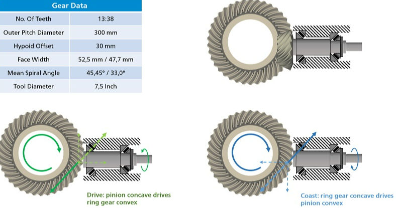 Figure 1: Gear data and tooth forces for drive and coast
For the drive side the concave pinion flanks move the convex ring gear flanks. The normal force of a pinion tooth, which is generated by the drive torque of the engine, is counteracted by the counterforce of the ring gear tooth of the same magnitude. This force acting on the pinion can be divided into two directions: an axial direction, which presses the pinion into the tapered roller bearing behind the pinion head, and a vertical direction, which acts against the axial offset of the pinion. This is a benign load case, since the limited rigidity of bearing and housing will move the pinion away from the center of the gearbox with an increase of backlash and tip-root clearance. In addition, the axial rigidity for the pinion shaft away from the gear center (to the right in Figure 1) is much greater than in the other direction.
In case of the coast side, the tooth forces will move the pinion into the gearbox. Here, in addition to increasing the axle offset, the pinion in Figure 1 is pulled to the left into the gear.
 Figure 2: Ease-Off, displacements and loaded contact patterns.
 Figure 3: Loaded contact pattern at 1,500 Nm torque.
 Figure 4.1: Plunging position
 Figure 4.2: Modified plunging position.
 Figure 5: Influence of several intermediate plunging positions connected by a smooth machining motion.
 Figure 6: Steps in Ease-Off development.
 Figure 7: KIMoS result of the optimized hypoid gear set for an electrically driven axle.