Research Objective and Approach
The research objective for generating
gear grinding at WZL is the increase of
process efficiency and process reliability
in generating gear grinding by description
of the technological cause-effect
relationships for cutting forces as well
as for occurrence of grinding burn in a
model. For the analysis of the cause-effect
relationships an analogy trail has been
developed and will be introduced in this
report.
The aim of this report is to present a
model to predict grinding burn for generating
gear grinding. Therefore cutting
forces in analogy trails are measured and
the interactions between process parameters
and occurred grinding burn are
taken into account. The measured cutting
forces will be combined in an empirical
cutting force model. With the ability
to calculate the cutting force the heat
flow density towards the workpiece can
be estimated. With a comparison of the
heat flow density and the grinding burn
occurrence a critical heat flow density
that leads to grinding burn can be determined.
Thereby a model to predict grinding
burn can be derived. In conclusion
the prediction model will be transferred
onto generating gear grinding and will
be validated by generating gear grinding
trials.
Analogy trail for Generating Gear
Grinding
The complexity of the contact conditions
between tool and workpiece during
generating gear grinding complicates
the analysis of generating gear grinding.
On the one hand, the penetration volumes
change over the tooth profile height
during grinding. On the other hand, the
number of engaged tool flanks and workpiece
flanks is variable. To investigate
generating gear grinding on a single fixed
point on the tooth profile, a geometrickinematic
model, the analogy trail, has
been developed (Refs. 12, 9). The principle
of the analogy trail for generating gear
grinding is shown (Fig. 2).
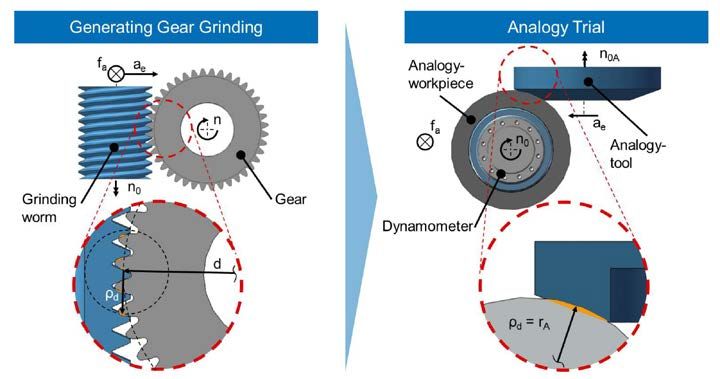
Figure 2 Analogy trial for generating gear grinding: principle and deduction of analogy
workpiece geometry (Ref. 9).
For each point of the involute the local
radius of curvature ρy can be calculated
(Ref. 13). For the analogy trail the contact
conditions at different positions of the
involute can be approximated. The radius
of the workpiece in the analogy trail
rA equals the radius of curvature at the
investigated point of the involute profile.
Thus the diameter of the analogy workpiece
depends on the number of teeth z,
the module mn, the helix angle β and the
pressure angle αn of the mapped sample
gear. The rack profile of the grinding
worm can be approximated in the investigated
contact point by a face wheel with a
conic working surface (Ref. 9).
Besides the workpiece and the tool
geometry the chip geometry in the analogy
trail has to be comparable to the chip
geometry in generating gear grinding.
Therefore the cutting length lcuA and the
chip thickness hcuA have to be comparable
between analogy trail and generating gear
grinding.
Furthermore the kinematics of chip
formation and the velocities must be fitted
to generating gear grinding. During
chip formation the lateral sliding speed
vtA, the axial feed speed vaA and the cutting
speed vc interfere with each other.
The cutting speeds in generating gear
grinding and analogy trail are the same.
The lateral sliding speed vtA can be calculated
by the rotational speed nA of the
workpiece and the requirement to be
synchronous. The axial feed speed vaA
can be adjusted according to the generating
gear grinding process as the product
of rotational speed nA and axial feed fa.
Rotational speed as well as axial feed in
analogy trail and generating gear grinding
is identical. The tool is a grinding
wheel with an angled surface. The angle
corresponds to the pressure angle αn0 of
the grinding worm.
The mapped grinding process and the
machine tool used are shown (Fig. 3).
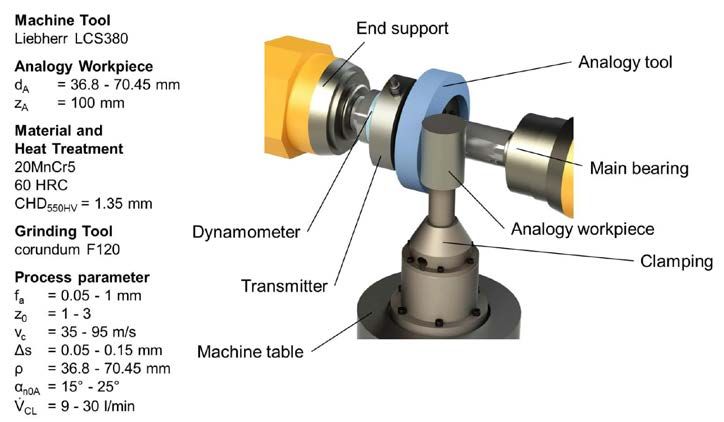
Figure 3 Workpiece data and machine tool.
The mapped grinding process is carried
out with a spur gear with a number of
teeth of z = 31 and a normal module of
mn = 4.5 mm. The material is 20MnCr5.
The gears are case-hardened with a surface
hardness of 60 HRC and a case-hardening-
depth of CHD550HV = 1.4 mm.
The material and heat treatment of the
analogy workpieces match the spur gears.
All generating gear grinding and analogy
trails were performed on a model
LCS380 grinding machine from Liebherr-
Verzahntechnik GmbH that can perform
both generating and profile gear grinding.
For both analogy and generating gear
grinding trials, corundum tools with a
grain size F120 (average grain diameter
109 μm) from Winterthur Technology
AG are used.
The experimental set-up of the analogy
trails is shown (Fig. 4);
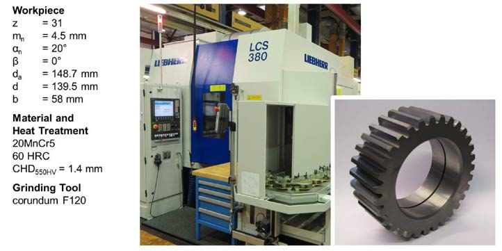
Figure 4 Experimental set-up analogy trial generating gear grinding.
the cutting force
can be determined with a dynamometer
which is integrated in the flow of forces.
For further information, a full description
of the analogy trail design can be
found in (Ref. 12).
With this experimental set-up, 129
analogy trails were performed. In these
analogy trails the following process
parameters were taken into account. The
axial feed fa, the number of starts z0, the
cutting speed vc, the stock Δs, the pressure
angle of the analogy tool αn0A and
the cooling lubricant volume flow VCL.
In addition, the diameter of the analogy
workpiece was varied to investigate different
points on the involute profile.
Prediction Model for Surface
Zone Inducements
Based on the empirical data of the analogy
trails an empirical-physical model
is built up in the following. Using the
model, the occurrence of a process-related
damage of the surface zone can be
predicted. For this purpose, an approach
to describe the surface zone inducement
is presented. Subsequently the required
parameters are determined and the prediction
model is derived.
Analytical model approach. To predict
the surface zone inducement the heat
flow density, which describes the energy
flow in the contact zone between tool and
workpiece, must be determined. To prevent
grinding burn the heat flow density
towards the workpiece qw must always be
lower than a critical heat flow density qw,
crit that leads to a detrimental influence on
the surface zone.
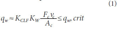
The heat flow density towards the
workpiece qw corresponds to the current
energy flow through the contact area
between tool and workpiece Ac. In general
for grinding the majority of the cutting
energy is thermal energy, which is
produced by intense friction, shear and
separation processes as well as by friction
of the abrasive grain and bond (Ref.14).
Assuming that also for generating gear
grinding almost all cutting power is converted
into thermal energy, the total energy
flow in the contact area can be calculated
by the product of cutting force
Fc and cutting speed vc. In order to estimate
the heat flow density towards the
workpiece qw correction factors must take the distribution of the heat flow from the
contact zone into account. These corrections
factors are KCLF which takes into
account the cooling lubricant flow and
KW which considers the heat flow towards
the workpiece. With these factors the heat
flow density towards the workpiece qw can
be estimated with Equation 1(Ref. 15) as:
Determination of model parameters.
In the following, the correction factors
KCLF and KW, the cutting force Fc and the
contact area between workpiece and tool
Ac must be determined to calculate the
heat flow density. With correlation of the
known heat flow density and the occurrence
of grinding burn for every trial the
critical heat flow density can be determined
Cutting Force
The cutting force was measured during
the analogy trails with a dynamometer.
During the analogy trails various process
parameters were investigated to get
a statement about the influence on the
cutting force. In order that the cutting
force does not have to be determined
empirically for each combination of process
parameters, a cutting force model is
derived in the following.
The cutting force model is set up based
on the obtained data from the analogy
trails using a regression analysis. For
regression analysis, the influence of the
process parameters axial feed fa, number
of starts z0, cutting speed vc, stock
Δs, cooling lubricant flow VCL and tool
pressure angle αn0A are considered. The
regression analysis of the cutting force is
carried out with a cubic approach considering
the interactions. For regression
analysis, the significance level was set to
α = 0.05. The comparison of the calculated
forces using the force model and
the measured forces is shown (Fig. 5).
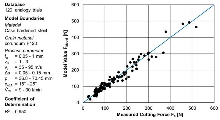
Figure 5 Model results and observations of the cutting force.
Good correlation between calculated and
measured forces is evident; this is confirmed
by a coefficient of determination
of R2 = 0.950.
In summary it can be stated that the
cutting force model maps the measured
cutting forces very well and offers a high
stability due to a widely varying database.
Thus, the cutting force model is suitable
as a basis for calculating the heat flow
density and to derive a prediction model
for surface zone changes for generating
gear grinding.
Contact Area
To define the heat flow density the contact
area between tool and workpiece
must be calculated. The contact area
Ac between tool and workpiece is corresponding
to the zone of heat transfer
between tool and workpiece. The contact
area for the analogy trails can be calculated
with a penetration calculation considering
various stocks and axial feeds.
Figure 6 shows the contact area for a constant
pairing of tool and workpiece over
axial feed. For an axial feed of fa < 0.2 mm,
the contact area drops sharply. For an
axial feed of fa < 0.08 mm no penetration
volume between workpiece and tool
could be calculated with the penetration
calculation.
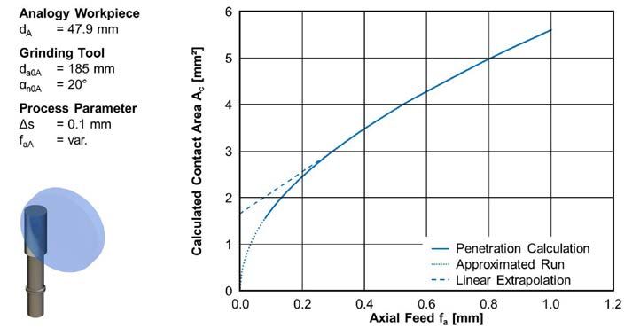
Figure 6 Determination of contact area.
Due to numerical inaccuracies, the calculated
contact area for small axial feeds
is not exact. From kinematics it can be
derived that in the absence of axial feeding
a contact between tool and workpiece
must exist for the first rotation of tool
and workpiece. The contact area for low
axial feeds of fa < 0.25 mm is calculated
from an axial feed by linear extrapolation.
The extrapolated contact area is indicated
by the dotted line in the diagram. Using
this functional relationship, the contact
area Ac can be determined for the prediction
model.
Correction Factors
Finally, the two correction factors to
calculate the heat flow density must be
determined. The heat distribution for
each combination of tool, workpiece and
cooling lubricant is different and variable
over the contact zone (Ref. 16). Due to
the different thermal material parameters
such as specific heat capacity cp and thermal
conductivity λ, as well as the inability
to determine the temperatures in the con-
tact zone, the heat distribution factor KW
cannot be calculated for generating gear
grinding. In several studies heat distribution
factors have been estimated for different
grinding processes (Refs.17–22).
The evaluation of these papers shows that
up to 80% of the thermal energy can flow
into the workpiece. For surface grinding
of unhardened steel a heat distribution
factor KW = 0.65 was determined (Ref. 19).
A heat distribution factor for grinding of
hardened 20MnCr5 cannot be found in
the literature. Because of the poor accessibility
of the contact area during generating
grinding a heat distribution factor
KW = 0.8 is assumed in this work. This
corresponds to the standard assumptions
in literature and provides an assessment
on the safe side (Refs. 23–24).
In addition to the constant heat distribution
factor KW, a variable factor KCLF
to determine the influence of the cooling
lubricant flow is necessary. For this purpose,
the heat flow densities of the analogy
trails were normalized to the maximum
heat flow density and analyzed
in relation to the cooling lubricant flow.
Using a regression analysis the influence
of the cooling lubricant flow on the heat
flow density was determined.
The normalized heat flow density qnorm
at constant process parameters decreases
with increasing cooling lubricant flow
(Fig. 7).
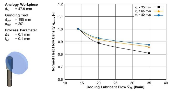
Figure 7 Determination of correction factor for consideration of cooling lubricant.
This effect is based on the better
supply of the contact area with cooling
lubricant. With increasing cutting
speed, the influence of the cooling lubricant
flow decreases. The rotation of the
tool produces a flow of air, which deflects
the coolant. The higher the cutting speed
the greater the cooling lubricant is dispersed
and the worse the contact area is
supplied with cooling lubricant (Ref. 6).
Therefore, the correction factor for the
cooling lubricant, which represents the
influence of the cooling lubricant flow on
the heat flow, is dependent on the cutting
speed vc as well.
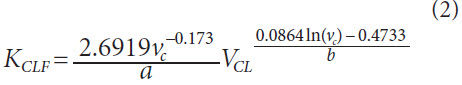
For constant cutting speeds, the heat
flow towards the cooling lubricant can
be approximated by an exponential function
depending on the cooling lubricant
flow VCL. The correction factor KCLF can
be described by Equation 2. The factors
a and b were determined as a function of
cutting speed using regression analysis.
The coefficient of determination for the
equation of the correction factor KCLF is:
The energy flow towards the workpiece
can be estimated by the product of the
two correction factors KW, KCLF and the
cutting power. Depending on the cutting
speed and cooling lubricant flow, the percentage
of the energy flow towards the
workpiece is between 60% and 80% of the
total cutting power.
Empiric analytical prediction model.
Based on the empirical knowledge of cutting
force and the analytical considerations
of an analytical heat flow density
an empirical-analytical prediction model
is derived in the following. The model is
used to predict the process-related influences
on the surface zone taking into
account the heat flow density towards the
workpiece.
Using the presented empirical force
model and the mathematical description
of the model parameters, the heat flow
density can be calculated for every trial.
In addition to the magnitude, the residence
time of the heat flow density also
has a major impact on the influence on
the surface zone. The residence time of
the heat flow density for one point on the
surface equals the contact time tc between
tool and workpiece for the same point.
The contact time for generating gear
grinding can be calculated with Equation
3, (Ref. 25).
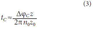
As with tool and process variables, the
contact time is also dependent on the
workpiece geometry. The contact time is
calculated by the rotational speed of the
tool n0, the number of starts z0, the number
of teeth of the workpiece z and the rolling angle of the cutting width Δφc.
The rolling angle describes the required
arc segment, which must be passed in
order to achieve the width of contact
between tool and workpiece at the
respective profile point.
For the analogy trails, the heat flow
density is plotted against the contact time
(Fig. 8).
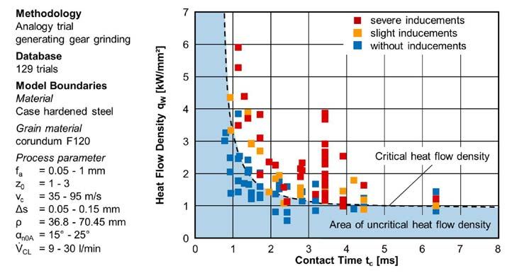
Figure 8 Surface zone inducements depending on heat flow density.
For this purpose, the heat flow
density was calculated for each point of
the analogy trails. The workpieces from
the analogy trails are marked in different
colors according to the type of influence
on the surface zone. Points that have
been highlighted in yellow and red show
a slight to strong influence on the surface
zone of the analogy workpiece. Points
marked in blue represent non influenced
surface zones. As a detection method
nital etching was used. For disposition of
detrimental surface zone inducements an
additional quantitative damage classification
was performed using the measurement
of Barkhausen noise.
The analysis shows that for a short contact
time a high heat flow density can
flow into the workpiece without causing
damage. In contrast, at long contact
times only a low heat flow density is necessary
to harm the surface zone. With
increasing contact time, the critical limit
asymptotically approaches a constant
level. From this distribution, the contact
time depending limit of the critical heat
flow density can be determined from the
graph and described mathematically.
The calculated critical heat flow density
is shown as a black dashed line in
the graph. Considering the simplified
assumptions for the calculation of the
correction factors as well as the contact
time and the dispersion of results, a very
well approximation for determining the
critical heat flow density can be found.
In summary it can be stated that the
empirical-analytical model is suitable to
determine the critical limit, which leads to
grinding burn. However, it must be determined
whether the model, which is based
on analogy trail results, can be applied to
actual generating gear grinding. For this
purpose, the prediction model must first
be validated with the sample gear that is
mapped in the analogy trail.
Validation of the Prediction
Model
The prediction model constructed on
basis of analogy trails is compared and
validated in the following with results
from generating gear grinding trials.
First, the transferability of the model to
generating gear grinding is validated. For
this purpose grinding tests are carried
out with the sample gear that is mapped
in the analogy trail. Subsequently, the
model is validated on an additional gear.
Transfer to generating gear grinding.
For the validation of the prediction
model a deductive approach is chosen
in the following. The general model was
applied to a particular case to validate the
findings. For the gear that is mapped in
the analogy trail, the heat flow densities
have been calculated for each set of process
parameters. The classification of heat
flow densities and surface zone inducements
in the analytical empirical prediction
model is shown in Figure 9.
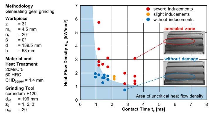
Figure 9 Model validation for sample gear.
The results of generating gear grinding
trials were arranged in the characteristic
field of the heat flow density of the prediction
model. The heat flow densities
shown are calculated for the pitch circle
diameter of the sample gear. The degree
of influence on the surface zone has been
marked in analogy to the previous illustrations.
The range of non-critical heat
flow density is identical due to the geometric
relationship between analogy trail
and sample gear.
All points for which no detrimental
surface zone inducement was observed
after generating gear grinding are with
one exception within the non-critical
area. The heat flow densities of the components
with slight and severe detrimental
inducements are larger than the calculated
critical heat flow density of the prediction
model.
The evaluation shows that the prediction
model is able to predict the occurrence
of grinding burn in good accuracy
for the sample gear. The results of the
generating gear grinding trials reflect the
determined findings and identified relationships
from the analogy trail. Thus,
the prediction model has been validated
for the sample gear. Whether the prediction
model can be applied to additional
gears must be examined in the following.
Validation with additional gears. In
order to test the transferability of the
empirical-analytical prediction model,
the model is applied to another spur gear.
Therefore further generating gear grinding
trials were performed.
The design of experiments was defined
by using the prediction model. For this,
the process parameters were predicted
for both clearly damaged and not affected
tooth flanks. The gears have been
inspected after grinding by means of nital
etching to evaluate and document surface
zone inducements.
As a second application a planetary
gear of a construction machine is selected.
In contrast to the previous gear, the
present gear has a higher module and a
higher face width. The gear geometry and
further details of material and heat treatment
can be found in Figure 10.
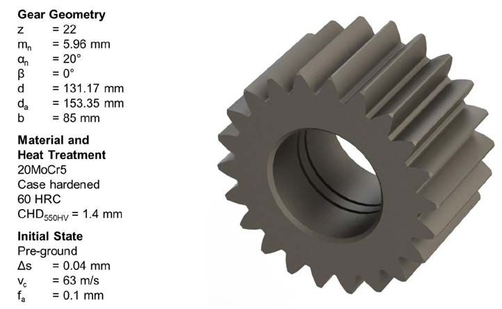
Figure 10 Gear geometry of planetary gear.
The results of the second gear geometry
are shown (Fig. 11);
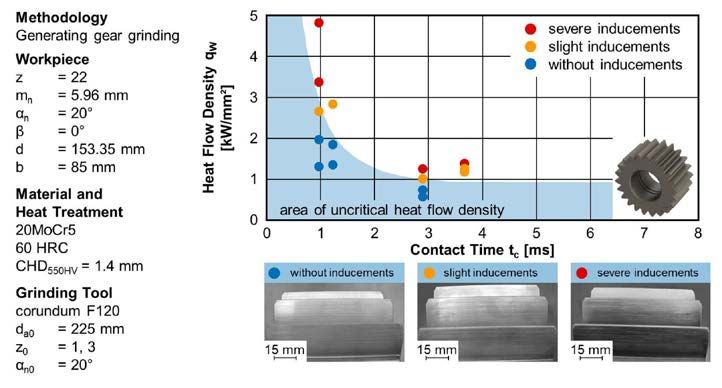
Figure 11 Application of prediction model for planetary gear.
for these trials tools
with different number of starts were used.
The calculated critical heat flow density
for the pitch circle diameter limits the
damaged and non-damaged gears with a
good accuracy. Different forms of surface
zone inducements are shown in the lower
part of Figure 11. All workpieces with a
detrimental inducement show a damaged
zone near the tip area.
Severely damaged components show
a dark coloration over a large part of
the profile. In addition to the qualitative
statement about whether surface zone
damage is to be expected, the heat flow
density can be calculated on the basis of
the local approach for any point of the
gear flank.
To explain the process-related detrimental
inducement in the tooth tip area,
the distribution of the heat flow density
has been calculated for a process design
for the entire tooth profile. The results
are compared with results of nital etching
in Figure 12.
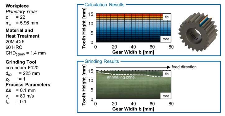
Figure 12 Comparison of local heat flow density and process results.
The occurrence probability of a surface
zone inducement is marked in color
on the tooth height. In the black and blue
areas no surface zone inducement is to be
expected. In the transition between the
light blue and the yellow area there may
be a slight damage. In the tooth tip area,
the critical heat flow density is exceeded
and therefore a damaged surface zone is
expected. This area is marked in red.
The distribution over the tooth height
can be explained by the cause-effect relationships,
determined in the analogy
trails. With an increase in the radius of
curvature the cutting forces increase as
well. This results in a varying heat input
over the tooth profile. The highest cutting
force and therefore the largest heat flow
density on the tooth flank is present at
the tooth tip. This result is well-correlated
with the results of nital etching.
In feed direction the affected zone is
growing in contrast to calculation results.
The main reason for the expansion of
the damaged zone is wear of the grinding
worm. With increasing machining
time also the friction and therefore the
cutting force as well as the heat flow density
increases. In the prediction model the
wear of the grinding wheel is not taken
into account. For this reason, predicted
and actual damage differ.
By applying the predictive model to an
additional gear, the applicability was tested
for other geometries. It turns out that
the prediction model derived from the
analogy trail can also be used to predict a
detrimental inducement of the surface for
additional geometries.
Summary and Outlook
The thermo-mechanical surface zone
inducement is an important quality criterion
for functionality of gears. Also for
generating gear grinding it is necessary to
determine thermal and mechanical loads
and their influencing factors to avoid
damage of the surface zone.
The research objective of this report
was to derive a model to describe and
predict detrimental surface zone inducements
for generating gear grinding.
Therefore, the necessary model parameters
and correction factors were determined.
Subsequently, the model was validated
using two gear geometries.
The objective of this report was met
through validation of the predictive
model. The model for predicting detrimental
surface zone inducements will
help increase the efficiency and process
reliability of continuous generating gear
grinding and improve the description
and understanding of the technological
cause and effect relations.
In the next step the derived empirical
analytical prediction model should be
linked with a manufacturing simulation.
The combination of a local determination
of chip geometries and the automated
calculation of the existing model
parameters will allow widespread use
of the model in industrial applications.
Furthermore, it will significantly improve
the process design and optimization in
continuous generating gear grinding. In
addition, the cutting force model can be
extended with a link to a manufacturing
simulation. With the help of calculated
chip geometries it is likely possible to find
a correlation between chip geometries
and the measured cutting forces.
Besides the optimization of the model
a further development of the analogy
trail is possible. With the analogy trail, an
evaluation of the performance of grinding
worms for generating gear grinding
can be performed. So on the one hand, a
pre-selection of grinding worm specifications
is possible and on the other hand the wear behavior could be analyzed better
due to the simple geometry of the
grinding tool.

Dipl.-Ing. Matthias
Ophey studied mechanical
engineering at RWTH Aachen
University with a focus on
production engineering.
Upon graduation in 2013 he
became a scientific research
assistant in the gear
department of the Laboratory of Machine Tools
and Production Engineering (WZL). Ophey’s
research is dedicated to focusing on hard
finishing of gears — especially generating gear
grinding, and manufacturing-related properties.

Dr. Jan Reimann is a 2008
graduate of RWTH Aachen
University, having studied
mechanical engineering
with a focus on production
engineering. He began
working in 2008 — first
as scientific research
assistant and later as
team leader — in the gear department of the
Laboratory of Machine Tools and Production
Engineering (WZL). While there he has
published his doctoral thesis on generating
gear grinding. Today Reimann is a production
engineer at Siemens Mechanical Drives in
Bocholt, focusing on manufacturing technology
development.
References:
- Schlattmeier, H. Diskontinuierliches
Zahnflankenprofilschleifen mit Korund,
Dissertation, RWTH Aachen, 2003.
- Meijboom, L. Erhöhung der Wirtschaftlichkeit
beim Wälzschleifen durch Verbesserung des
Zerspannvorgangs, Dissertation,
RWTH Aachen, 1979. 3. Türich, A.
Werkzeugprofilerzeugung für das
Verzahnungsschleife, Dissertation, Universität
Hannover, 2002.
- Bausch, T., Moderne Zahnradfertigung.
Verfahren und Maschinen zur kostengünstigen
Herstellung von Stirn- und Kegelrädern mit hoher
Qualität, 3. Auflage, Expert Verlag, Renningen-
Malmsheim, 2006.
- Stimpel, F.Technologische Kenngrößen
für das kontinuierliche Wälzschleifen von
Evolventenverzahnungen, Dissertation,
Universität Hannover, 2009.
- Klocke, F. and König, W., Fertigungsverfahren
Band 2: Schleifen, Honen, Läppen. 4. Auflage,
VDIVerlag, Düsseldorf, 2005.
- Reichel, F. Verfahrensauswahl beim Schleifen von
Großverzahnungen, Seminar: Feinbearbeitung
von Zahnrädern, WZL der RWTH Aachen,
November 2007.
- Sulzer, G. Werkzeugmaschinen zum
Feinbearbeiten der Zahnradflanken von vorverzahnten
Zahnrädern, Europäische Patentschrift
EP0282046, Liebherr Verzahntechnik, Kempten,
1993
- Klocke, F., C. Gorgels, and J. Reimann.
Generating Gear Grinding – New Possibilities
in Process Design and Analysis, AGMA Fall
Technical Meeting 2011, 11FTM02, ISBN 978-1-
61481-001-8.
- Klocke, F., C. Gorgels and J. Reimann. Analyse
des kontinuierlichen Wälzschleifens mithilfe der
Durchdringungsrechnung, In: 50. Arbeitstagung
„Zahnrad und Getriebetechnik“, Hrsg.: Klocke,
F.; Brecher, C., Eigendruck Getriebekreis
Aachen, S.14-1 - 14-40, 2009.
- Klocke, F., C. Gorgels and J. Reimann.
Kontinuierliches Wälzschleifen von Verzahnungen
– Softwareunterstützte Prozessoptimierung, In:
WB Werkstatt und Betrieb, Jg. 142, Heft 5, S.62-
63, 2009.
- Klocke, F., C. Gorgels and J. Reimann. Ansatz
für ein Prozesskraftmodell für das kontinuierliche
Wälzschleifen von Verzahnungen, In: 51.
Arbeitstagung „Zahnrad und Getriebetechnik“,
Hrsg.: Klocke, F.; Brecher, C., Eigendruck
Getriebekreis Aachen, S.8-1 - 8-40, 2010.
- DIN 3960. Begriffe und Bestimmungsgrößen für
Stirnräder (Zylinderräder) und Stirnradpaare
(Zylinderradpaare) mit Evolventenverzahnung,
Hrsg. Deutscher Normenausschuss, März 1987.
- Vits, R. Technologische Aspekte der
Kühlschmierung beim Schleifen, Dissertation,
RWTH Aachen, 1985.
- Takazawa K. Effects of Grinding Variables on
Surface Structure of Hardened Steel, In: Bulletin
of the Japan Society of Grinding Engineers,
Volume 2, S. 14-21, 1966.
- Hoffmeister, H.-W and B. Denkena. Jahrbuch
Schleifen, Honen, Läppen, Polieren: Verfahren
und Maschinen, Vulkan-Verlag, Essen, 63.
Ausgabe, ISBN 3-802-72941-2, Oktober 2007.
- Gorgels, C. Entstehung und Vermeidung
von Schleifbrand beim diskontinuierlichen
Zahnflankenprofilschleifen, Dissertation, RWTH
Aachen, 2011.
- Grof, H.E. Beitrag zur Klärung des Trennvorgangs
beim Schleifen von Metallen, Dissertation, TU
München, 1977, 15 14FTM02.
19. Hoffmeister, H.-W. and H.K. Tönshoff. Jahrbuch
Schleifen, Honen, Läppen, Polieren: Verfahren
und Maschinen, Vulkan-Verlag, Essen, 61.
Ausgabe, 2004.
- Lowin, R. Schleiftemperaturen und ihre
Auswirkungen im Werkstück, Dissertation,
RWTH Aachen, 1980.
- Rowe, W.B., S.C.E. Black, B. Mills, H.S. Qi and
M.N. Morgan. Experimental Investigation of
Heat Transfer in Grinding, In: Annals of the
CIRP, Volume 44/1/1995, S. 329-332.
- Steffens, K. Thermomechanik des Schleifens,
Dissertation, RWTH Aachen, 1983.
- Heinzel, C. Schleifprozesse verstehen: Zum
Stand der Modellbildung und Simulation sowie
unterstützender experimenteller Methoden,
Habilitation, Universität Bremen, 2008.
- Tönshoff, H.K., J. Peters, I. Inasaki and T. Paul.
Modelling and Simulation of Grinding Processes,
In: CIRP Annals 41(2):677–688, 1992.
- Schriefer, H., W. Thyssen, W., Wirz, G. Scacchi
and M. Gretler. Kontinuierliches Wälzschleifen
von Verzahnungen, 1. Auflage, Eigenverlag
Reishauer AG, Wallisellen, 2008.


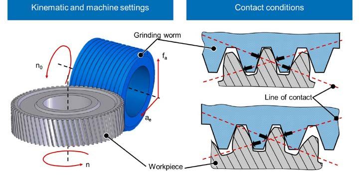 Figure 1 Generating gear grinding: principle, machine settings, and contact conditions (Ref. 9).