Francois Gerard, Business Development Manager, LMS Engineering Services
LMS International,an automotive consultancy, helped Elasis S.C.p.A., a Fiat subsidiary, develop a new, dynamic vibro-acoustic prediction method to reduce design time and engineering costs through accurate prediction of gear noise in the design phase. The method, based on a pure computer aided engineering (CAE) model, demonstrated the potential for reducing time and costs when LMS and Elasis were working on a new transmission project.
Currently, large amounts of time and money are spent during the prototype phase of powertrain development identifying and solving noise problems occurring under various operating conditions. Elasis and LMS worked together to simulate gearbox noise using a detailed CAE model that simulates noise generation mechanisms at the source.
Experimental testing was used at every phase of the modeling in order to validate the CAE modeling. This approach provides more information on the root cause of noise problems than even prototype testing and makes it possible to develop solutions earlier, faster and at a lower cost.
As automobile manufacturers continue to substantially reduce engine and road noise, the transmission is becoming of much greater importance as its noise is less and less masked by other sources. Transmission designers must address noise problems occurring in many different conditions, such as clutch clunk noise, gear whine, gear rattle, driveline boom, etc. Two major classes of gearbox noise encountered in practice are gear whine and gear rattle.
Major Noise Generation Mechanisms
Gear whine is a tonal noise that occurs at orders of engine rpm which correspond with the number of teeth in the different gear pairs. Gear whine can result from several causes, a main one being errors in manufactured tooth geometry or shape, another one being excessive intentional modifications to tooth shape (like tip and root relief) that affect conjugacy in mating pairs of gears. However, gear whine is also caused by variation in the rotational stiffness of contact between two gear pairs. This stiffness varies as a function of time for two different reasons. The number of teeth in contact can vary through each revolution, with two teeth being in contact at one point in time and three at another, for example. Also, the point of contact on a given gear pair continually moves along the face of the teeth. One can view each tooth as a beam that is clamped at its root. The bending stiffness of these beams changes as the contact point moves along the beam. For one given tooth, the stiffness rises as the contact point moves towards the root diameter and falls as the contact point moves towards the outer diameter. This phenomenon accounts for additional stiffness variation as a function of time.
Gear rattle results from the fact that non-power transmitting gears are free to move within boundary limits defined by the tangential clearance between the teeth of different gears and the radial and axial clearance between gear and shaft. These gears impinge upon other gears and shafts, resulting in metal-to-metal impacts. These impact forces generate a wideband vibration frequency content. The impacts are driven by engine speed fluctuations due to combustion forces. Gear whine and rattle sources are transferred to the shaft bearings, which finally excite the transmission housing. The housing vibrates and acts as a noise radiator.
Move from Build and Test to CAE
Today, transmission manufacturers typically address these problems by spending considerable time and energy during the prototype testing phase evaluating transmission noises occurring when gears are being shifted, as the engine is accelerated in various gears, while idling, etc. The problem with this approach is that it’s very expensive and time-consuming to build prototypes, perform physical testing and then modify the prototypes in an effort to solve the problem. Another problem is that the amount of information provided by physical testing is limited by the number and accuracy of sensors that can be used to instrument the transmission.Many important areas, such as the gear teeth, are difficult or impossible to instrument.
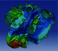
For these reasons, Elasis has in the last several years begun working to develop CAE methods to evaluate and understand gearbox noise in the design stage when prototypes are not available. The aim is to be able to optimize the design while reducing or eliminating the need for troubleshooting during the prototype phase. One approach that has been used successfully by LMS is to focus on the analysis of the transmission housing, analyzing how the transmission housing vibrates and radiates noise under known forces at the bearings and how this noise is transmitted to the vehicle interior. The transmission housing can be modeled using finite element (FE) and boundary element models, and the forces at the bearing can be identified by means of experimental methods, such as transfer path analysis. This combined test-CAE simulation can be used to identify weaknesses in the housing and make corrections such as adding ribbing, changing wall thickness, etc.
This method can be used based on forces identified on the current design of the gearbox, if the box is already available for testing, or with realistic forces defined from experience with similar types of gearboxes. This approach is appropriate when the noise problem lies in resonances of the gearbox housing, which amplifies the internal forces generated at the bearings. However, when the problem is mainly due to high excitation forces, the solution cannot always be found in structural housing modifications, and another approach must be used.
Eliminating Noise at its Source
Elasis is a Fiat-owned engineering company that works mainly for Fiat Auto and on the Fiat-GM Powertrain joint venture (FGP), carrying out research and development on vehicles and powertrains. In the current project, LMS and Elasis set out to go beyond the above method by analyzing in detail the sources of the noise in a new transmission. The challenge was modeling the full complexity of the internal operation of the transmission to the level of detail required to accurately predict internal dynamic forces in the wide frequency range associated with gear rattle.
LMS engineering specialists developed an approach that combines multibody simulation and boundary element analysis to capture the root causes of noise generation within the transmission. The first step was using LMS DADS software to create a dynamic model of the internal transmission mechanism that incorporates gear stiffness, gear backlash, bearing characteristics, and hub and sleeve connection properties. The flexibility of components, such as the shaft and housing, was represented by using modal parameters obtained from FE models.
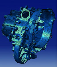
In the project, a constant stiffness at the contact of each pair of teeth was considered because the focus was mainly on gear rattle. Stiffness fluctuations due to the moving contact between teeth were neglected. However, when focusing on gear whine, it is possible to extend the procedure. A person can, for instance, use an analytical relationship that provides the stiffness of the tooth contact as a function of the parameters related to the contact location. This relationship can be incorporated into the model as a user-defined subroutine.
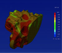
The next step was building a boundary element model of the housing using LMS Sysnoise software in order to predict the noise radiated under the simulated conditions.
Validating the Accuracy of the Model
The NVH department at Elasis has built a state-of-the-art test rig to evaluate manual gearboxes. Within the scope of this project, this test rig was used to identify the main source of gear rattle and to provide the necessary information and physical insights to the numerical modeling and analysis.
This test rig is a virtual engine simulator (VES), which has the ability to reproduce speed and torque fluctuations, up to 500 Hz, similar to those generated by a physical internal combustion engine. This simulator eliminates the need to have a real engine. Moreover, it ensures that the gearbox is the sole source of the recorded noise. This capability allows for an in-depth study of gear rattle noise and eliminates the mask effects of engine noise. Furthermore, the VES allows the "core" parameters to be changed to perform a parametric sensitivity study.
One important insight gained during the project is that velocity fluctuations at the engine shaft primarily increase gear rattle at low rotational speeds.
The input to the multibody simulation was 1.) the combustion pulsations represented by the engine speed fluctuations and 2.) the resistance torque as seen by the transmission, which represented the vehicle load. The multibody simulation was carried out in fifth gear, by inputting the rotational speed on the flywheel while applying a resistance torque at the output shaft. The gearbox housing acted as the noise radiator. Because the gearbox was simulated as a flexible component characterized by the modes of an FE model, the modal participation factors as a function of time were computed during the multibody simulation. They were transferred to the frequency domain and applied to the vibroacoustic model of the gearbox, which yielded the noise radiation prediction. The simulated results were compared to the measurements to validate the modeling approach.
This advanced modeling procedure can be used for optimization purposes, and a big advantage is that both the source parameters (gear clearance, contact stiffness) and the transfer path parameters (component inertia and flexibility, housing dynamics) can be investigated and modified with a view to improving the noise and vibration performance.
This method will enable Elasis to make better design decisions in the early phases of the development when prototype results are not available. It will also become possible to obtain far more detailed information on the performance of proposed designs and evaluate alternate decisions at much less time and expense compared to the build-and-test method. As was already mentioned, the modeling procedure can be extended easily to also simulate gear whine. As the new simulation methods are further refined and used more widely within Elasis, they should substantially improve the transmission design process.
For more information:
LMS North America
1050 Wilshire Blvd., Suite 250
Troy, MI 48084
Phone: (248) 952-5664
Fax: (248) 952-1610
E-mail: info@lmsintl.com
Internet: www.lmsintl.com
Comment on this article by sending e-mail to publisher@geartechnology.com