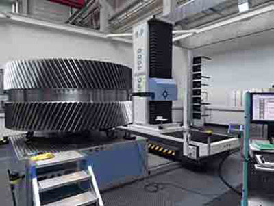
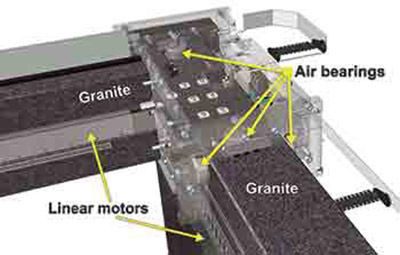
Granite has been used for highly accurate
CMMs and other measuring instruments
for many years. It offers a number
of benefits for accuracy-determining
components of industrial measuring
technology:
- Due to the age and origin, granite is
free of internal tensions and thus externally
stable in the long term
- The thermal expansion coefficient is
only about half that of steel and a quarter
of aluminum
- It is highly wear-proof, pressure-proof
and deforms 25% less under load than
an identical aluminum component – at
a higher specific weight of only about
5%
- Granite is non-magnetic, non-corroding,
and has vibration damping characteristics
- Proper processing produces nearly
pore-free, flat and level surfaces that
provide a solid basis for air bearing
guides — a well-established technology
that was a prerequisite for the ultimate
accuracy of coordinate measuring
equipment.
Hydrostatic rotary tables (Fig. 3) with
direct drive torque drive motors can provide
the precision required for measurement
of large diameters and heavy gears
up to 40,909 kg (90,000 lbs.). Hydrostatic
bearings have no metal-to-metal contact,
extremely low friction and virtually limitless
life. Conventional ball bearing tables
and air bearing tables typically have
much lower weight capabilities. These
well-proven and technically advanced
hydrostatic rotary tables are normally
used in large gear grinding machines.
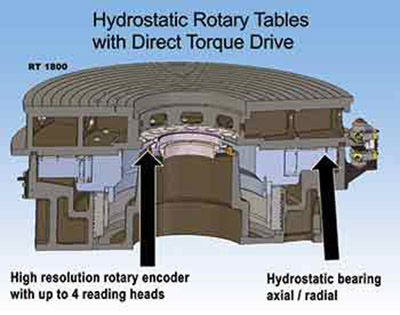
Figure 3 Hydrostatic rotary table.
- Click image to enlarge
Special mechanical solutions for the
rotary table and specific control measures
are needed for measuring large gears in
respect to polar inertia. The machine
needs to be able to accurately position a
part weighing 40,000 kg as well as one
weighing as little as 28g (1 oz). In addition
to the part’s polar inertia, the inertia
of the equipment’s workpiece support has
to be considered. In order to determine
the actual conditions, the gear inspection
system needs to be capable of automatically
adjusting multiple drive parameters
in order to gain accurate and repeatable
measuring results. This is accomplished
through the use of intelligent algorithms
and intelligent drives.
A special design of rotary encoder is
used for this large application. It has a
large diameter and utilizes up to four
reading heads and double-scale interpolation
for enhanced accuracy.
Thermal Stability
The larger the component and the longer
the inspection time, the larger the change
in size as a result of temperature change.
By using granite for the machine guideways,
this change is minimized due the
low coefficient of expansion and granite’s
relatively slow rate of change.
To compensate for deviations caused
by temperature change, the equipment needs to provide several temperature sensors
for the machine and workpiece, and
corresponding algorithms to consider the
temperature effects on the evaluation of
measuring data.
For production efficiency, inspection
equipment is typically installed close to
the production facilities. Due to equipment
size and location, workpiece transportation
methods and paths often lead
to a working environment with temperature
swings. To meet this challenge, large
gear inspection equipment must have
long-term thermal stability, temperature
compensation and way covers.
To achieve this stability, the base plate
and at least the Y and Z linear axes (used
for the needed motion for generative gear
inspection) should be of granite construction
to take advantage of the material’s low
coefficient of expansion and resistance
to the effects of temperature. Each axis
has temperature measurement equipment
built in, and a probe is used on the part
to measure the temperature. This data is
used to compensate for the temperature of
the part and the machine’s axes.
The ways are covered and create a
microclimate effect, which reduces temperature
variation. This damps rapid
transient fluctuations in temperature.
On large systems, these way covers are
also walkways for operator access to the
machine and workpiece.
Vibration Control
Rather than relying on an expensive special
foundation, a modern large gear
inspection system employs an active,
computer controlled, air suspension system
(Fig. 4). This isolates the machine
from vibrations in the shop environment
and keeps the machine constantly level.
This technology has been long proven
in high accuracy CMM applications for
many years.
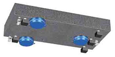
Figure 4 Air suspension vibration isolation.
- Click image to enlarge
A concrete floor or foundation is subject
to changes over time. Rather than
relying on the foundation or floor for
stability, a large gear measuring system
requires intrinsic stability independent of
the floor or foundation.
In addition to the stability it provides,
the active air suspension, with its effective
isolation, can substantially reduce
installation cost and allow more freedom
in locating the machine.
Mounting and Centering
In stark comparison to small gears,
large workpieces (externals or internals)
require intelligent, operator-friendly solutions
for safely mounting and centering
the parts. It is no longer necessary
or acceptable to use a huge hammer or
swinging ram to center heavy parts. Once
mounted, the system completes the fully
automatic procedure to determine the
axis of the workpiece.
Figure 5 shows a leveling table with a
cross-slide and the possibility to extend
the mounting range by means of extension
arms (spider).
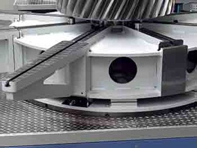
Figure 5 Mounting and centering.
- Click image to enlarge
The mounting and centering a heavy
part can be accomplished in four steps:
- Mount 3 “fix points” on the table in
positions provided by the machine
using built-in utilities
- Load part on the leveling table against
or near fix points for pre-positioning
- The system will automatically probe
the actual position of the part to determine
the needed movements of the
cross-slide
- Move the cross-slide axis by means of
monitoring the actual position on the
screen, shown in real time by the operator
software
In addition to the ease of use this provides,
a substantial time savings and efficiency
improvement is also realized. It is
also safer for operators and can reduce
the chance of damage to the part.
Safety
To protect operators from accidents
during the measurement process, large
gear inspection machines must provide
additional safety features not needed on
small- or medium-size machines. These
safety systems must be standard equipment
because safety is required and not
optional.
A PC-based intelligent laser system
(Fig. 6) allows customizable safety zones
around the machine and exclusion zones
for fixed areas like room columns. Signal
lights indicate the status of the machine.
If there is movement into the protected
area, layers of increasing audible and visible
warnings precede the last warning
with horn, and finally, an emergency stop
will occur.
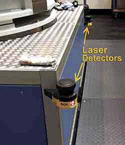
Figure 5 Mounting and centering.
- Click image to enlarge
Customized Versions – One Size
Does Not Fit All
Any gear measuring machines for workpieces
with diameters of 1,600 mm
and larger should fulfill all individual
demands of the customers and special
requests of the operators.
To provide this customization, R&P
Metrology GmbH uses modular design
by which individual machines are configured:
- Individualized design and size of granite
base plate to fit into existing facility
- Several options for vertical measuring
lengths
Rotary tables with different load capacities
using air bearings or hydrostatic
bearings as appropriate
Various tailstock lengths in fixed or
movable positions
Intelligent solutions for centering,
holding and clamping workpieces
Complete software library including
3-D software packages
Big Gears Require Special
Solutions
From the above discussion, it is clear
that large gear metrology requires careful
application of appropriate technologies
rather than just “supersizing” a standard
smaller gear checker.
Taken together as a system, the use of
intelligent algorithms for automatically
determining and controlling polar inertia,
granite guideways and air bearings,
hydrostatic rotary tables, thermal stability/
compensation and vibration isolation
combine to form the benchmark for
the current state-of-the-art in large gear
metrology. Controlling the large masses
involved, thermal stability, part centering
and alignment, safety and customization
all need to be taken into consideration and
addressed to produce accurate and reliable
gear inspection systems for large gears
About Author
Dwight Smith is the
Sales Manager for Kapp
Technologies, and product
manager for the R&P
Metrology line of large
gear measuring equipment,
which Kapp Technologies
distributes in North America.
He has over twenty-five years of experience
in the gear industry and gear metrology.
He chairs an AGMA committee and is an
instructor for the AGMA Basic Gear School,
and presents at the annual Kapp Niles Rocky
Mountain Gear Finishing School. For more
information about R&P Metrology machines
please contact Dwight Smith at 734-516-1365.


