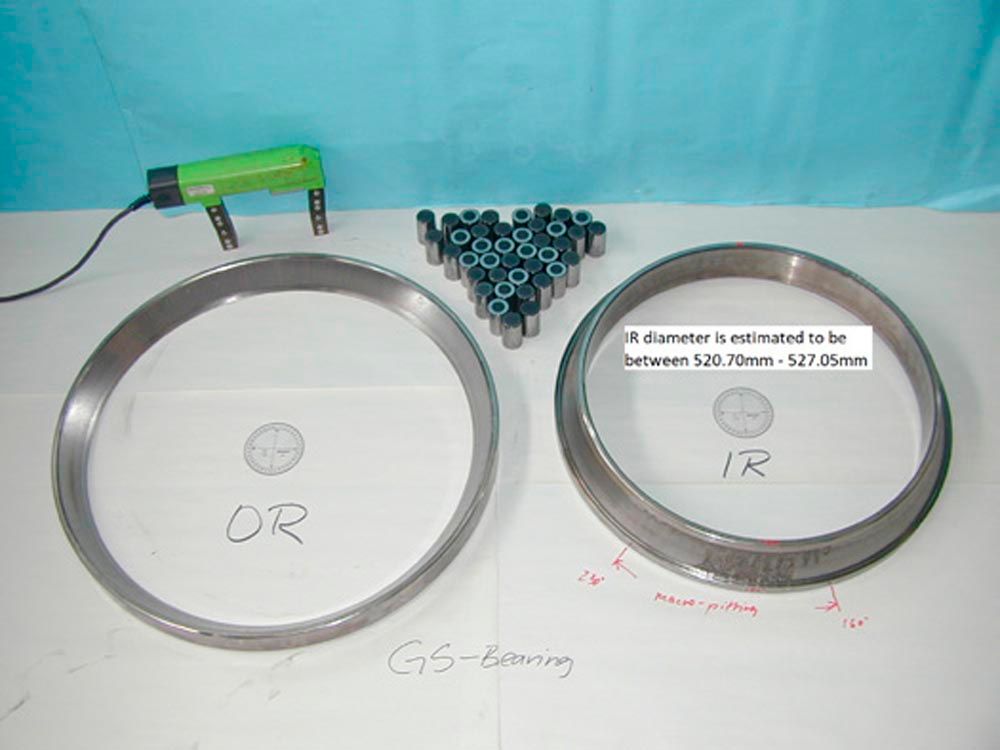
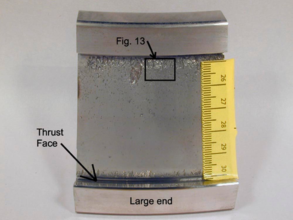
Figure 4 shows the section of the IR with severe macropitting.
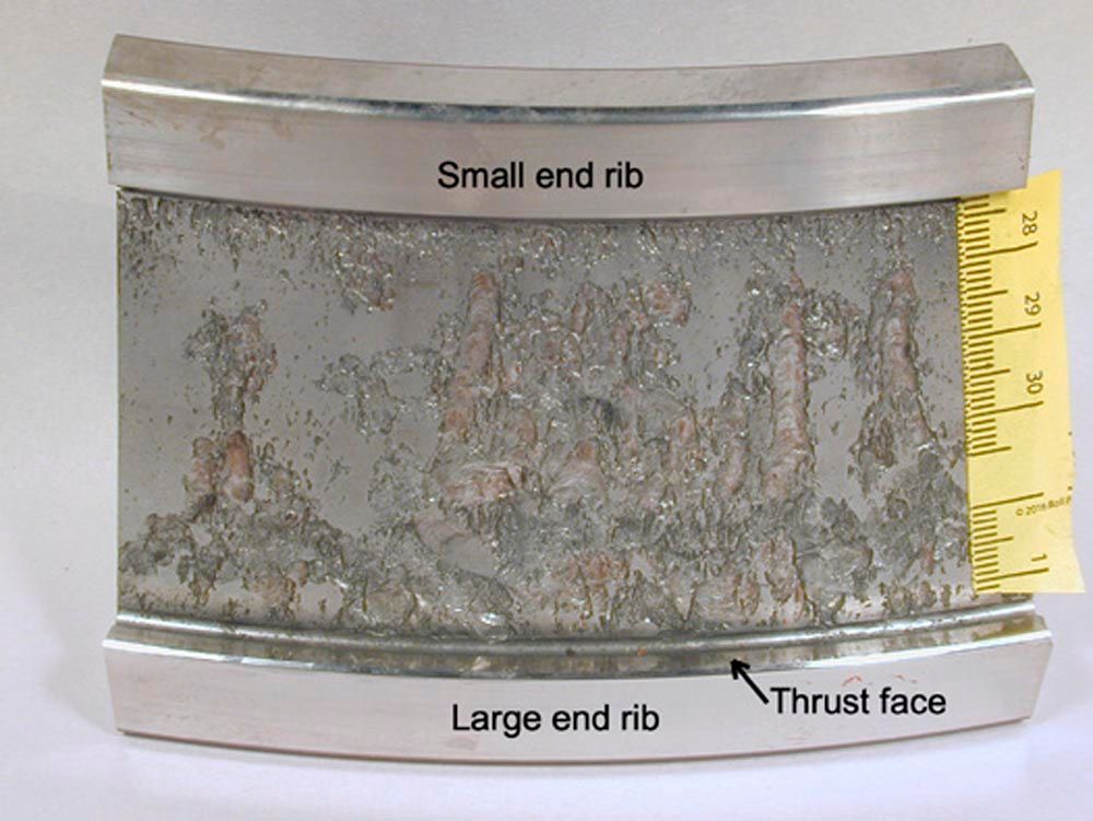
Figure 4—section of the IR with severe macropitting.
Description of Figure 4
Macropitting is a type of failure that often occurs after micropitting. This is because micropitting can damage the accuracy of some components, such as the OR, IR, and rollers, and increase the internal clearance of the bearing. When the components lose their accuracy and the internal clearance increases, the bearing can become misaligned, leading to GSC. One can identify macropitting by looking for beach marks left by fatigue growth and fretting corrosion in the craters caused by rubbing between the faces of the subsurface macropitting cracks.
It is important to recognize that micropitting is the primary failure mode, with macropitting being a secondary failure mode that occurs due to micropitting.
Figure 5 is a light optical microscopy (LOM) image of the face of the IR thrust rib.
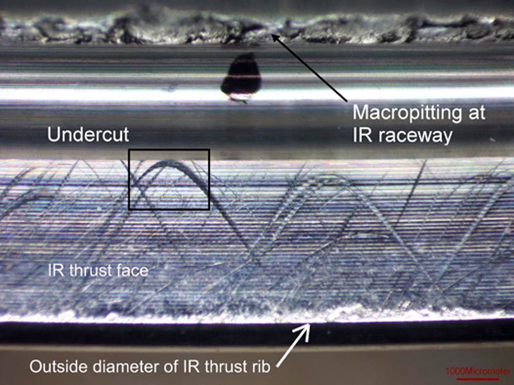
Figure 5—LOM image of the IR thrust rib.
Description of Figure 5
The macropitting at the edge of the IR raceway is at the top of the image and the outside diameter of the IR thrust rib is at the bottom of the image. The undercut of the grinding relief is between the macropitting and the face of the IR thrust rib. See Figure 21 for an enlarged view of the area within the rectangle.
The arc-shaped marks on the face of the IR thrust rib are grooving abrasions that were caused by hard particles that were trapped between the roller ends and the IR thrust rib. Each arc-shaped mark was caused by a particle that got fixed on the end of a roller and forced to follow a specific path called a curate epitrochoid (see “Annex A” section for description of epitrochoids). The various positions of the arc-shaped marks were caused by separate particles that were fixed at various positions on the roller ends.
Figure 6 is a LOM image of the large end of a roller with a multitude of scratches.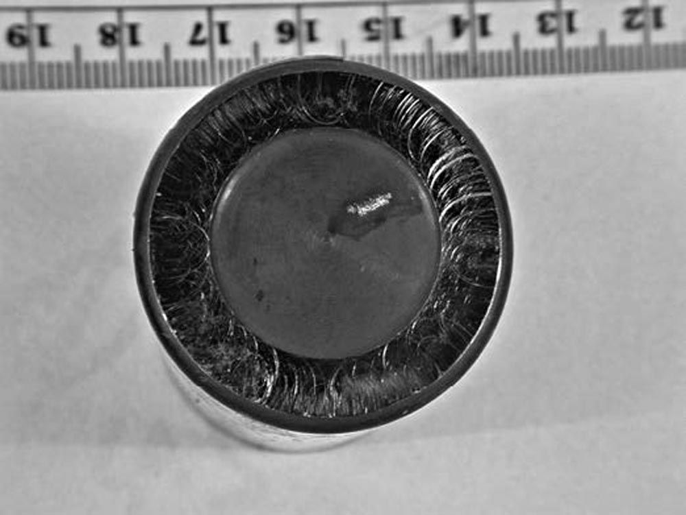
Figure 6—LOM image of the roller large end with a multitude of scratches.
Figure 7 is a LOM image that is an enlarged view of Figure 6.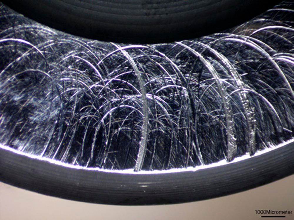
Figure 7—LOM image of an enlarged view of Figure 6.
Figure 8 is like Figure 7 except that a different lighting direction was used for the photo. LOM has an advantage over scanning electron microscopy (SEM) because scratches are emphasized by specular light reflection.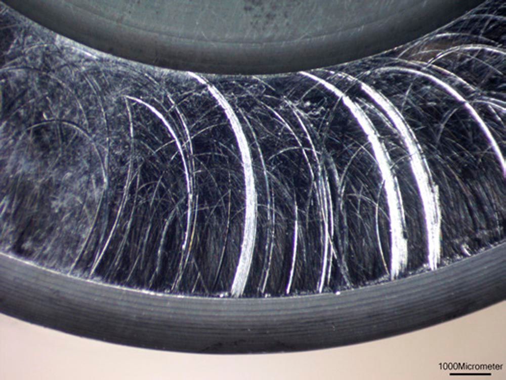
Figure 8—same as Figure 7 except with a different light direction.
Description of Figure 8
The recess on the roller end is at the top of the image, and the outside diameter of the roller is at the bottom of the image.
There are marks on the roller end face that are shaped like an ellipse. These marks were caused by grooving abrasion, which was caused by hard particles that got trapped between the roller end and the IR thrust rib. A fixed particle on the IR thrust rib traces an ellipse-shaped curve called a prolate epitrochoid on the end of the roller. The positions of the ellipse-shaped marks varied because separate particles were fixed at different positions on the IR thrust rib. If you want to know more about epitrochoids, see Annex A for a detailed description.
Figure 9 is a LOM image of the bearing OR. It shows micropitting biased toward the large end of the OR raceway and small macropits starting at the edge of the OR raceway.
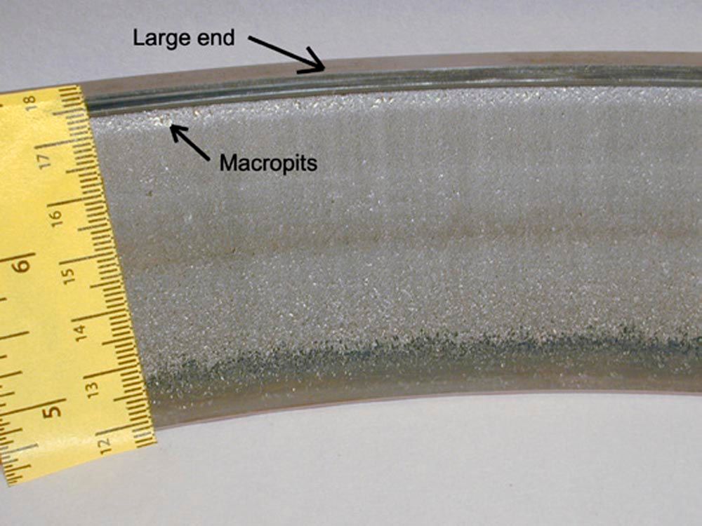
Figure 9—Micropitting biased toward the large end of the OR raceway.
Figure 10 is a LOM image of the bearing IR raceway at 10x magnification.
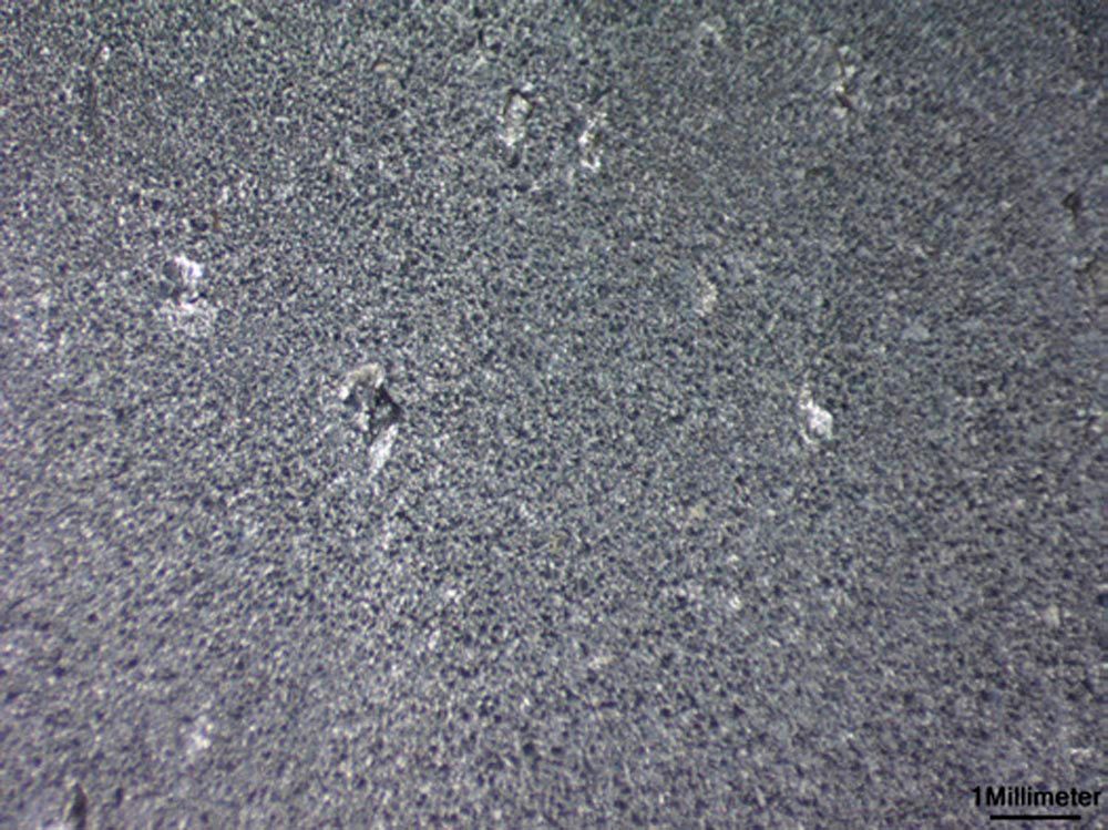
Figure 10—LOM image of the bearing IR raceway at 10x magnification.
Figure 11 is an SEM image of the IR raceway at 40x magnification.
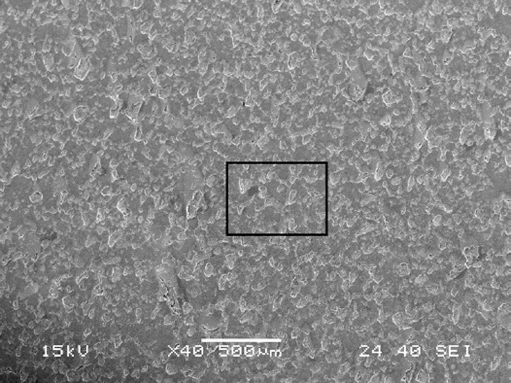
Figure 11—SEM image of the IR raceway at 40x magnification.
Figure 12 is an SEM image of the IR raceway within the area of the rectangle in Figure 11 at 200x magnification.
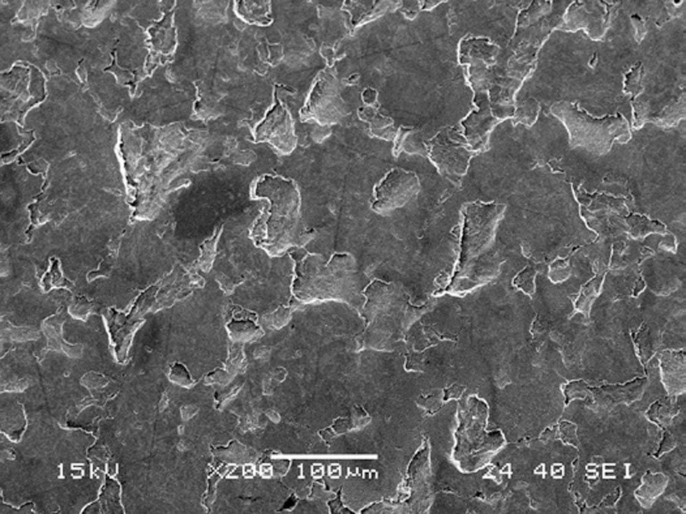
Figure 12—SEM image of the IR raceway at 200x magnification.
Figure 13 is an SEM image of macropitting at the edge of the small end of the IR raceway.
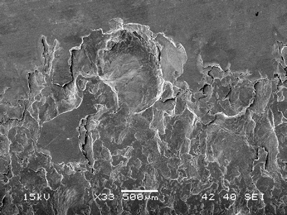
Figure 13—SEM image of macropitting at the edge of the small end of the IR raceway.
Description of Figure 13
Macropitting was detected at both edges of the IR raceway. Figure 13 shows macropitting at the small end of the IR raceway. This area is just to the right of the large macropit shown in Figure 3. The macropitting was caused by GSC, which occurred due to the abrupt edge of the micropitting on the IR raceway. Furthermore, the micropitting increased the internal clearance of the bearing, leading to misalignment and further aggravating the GSC.
Macropitting is a secondary failure mode that often occurs at the edges of bearing raceways, following the primary failure mode of micropitting. This occurs because micropitting causes the IR raceway to conform to the rollers and eliminates the crown on the rollers, which creates GSC at the ends of the rollers. For more detailed information on this mechanism, please refer to Ref. 3.
Figure 14 is the same LOM image as Figure 8, repeated here for clarity.
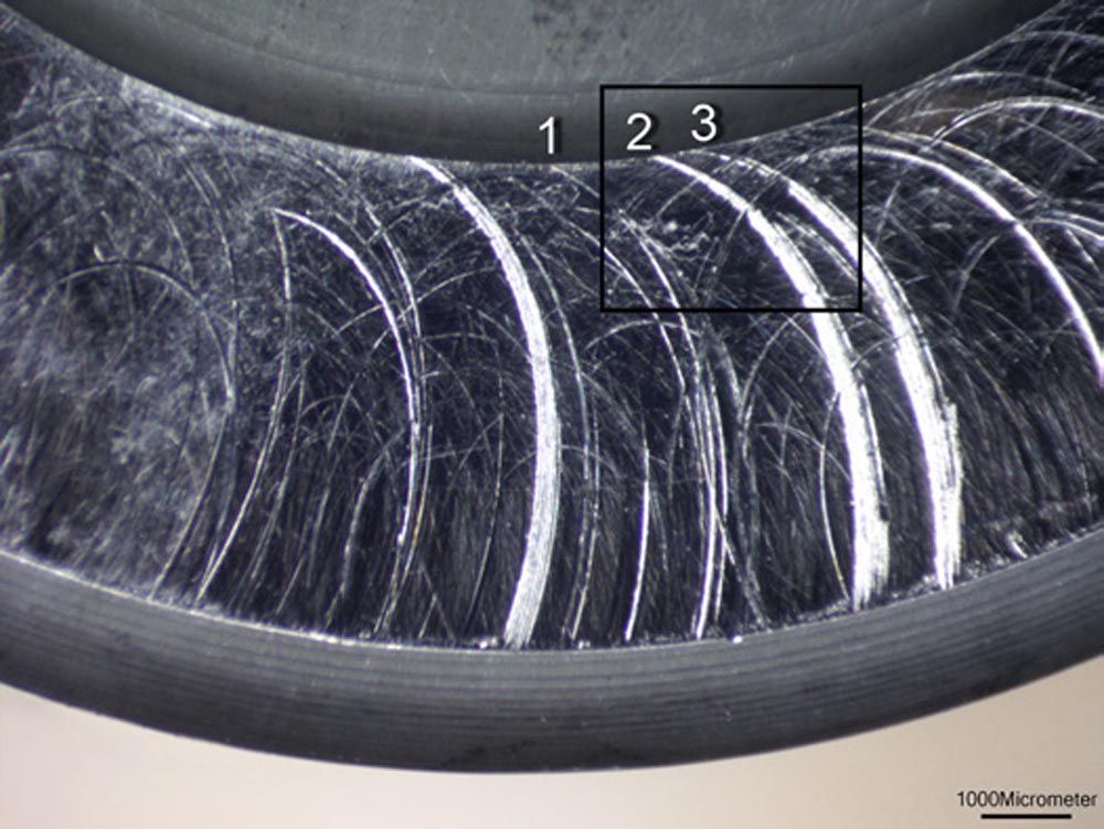
Fig 14—LOM image of roller end (same as Figure 8).
Description of Figure 14
For discussion, we identify three prolate epitrochoid curves—Curve 1, Curve 2, and Curve 3. Curve 1 is narrower than 30 µm and is referred to as a scratch, while Curve 2 and Curve 3 are wider (up to 400 µm) and referred to as grooves. During the grooving abrasion process, hard particles on the IR thrust rib begin contact with the roller end at the bottom of Figure 14 and leave contact with the roller end at the recess near the top of Figure 14. See Figure 15 for an enlarged view of the area within the rectangle.
SEM and BSE Images of Roller End Wear
The following Figures 15–20 are SEM images and backscattered electrons (BSE) images of roller end and IR thrust rib grooving abrasion.
Figure 15 is an SEM image of the roller end within the area of the rectangle in Figure 14 at higher magnification.
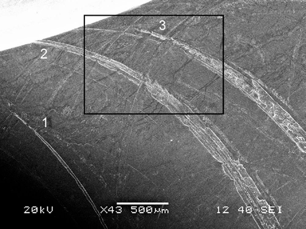
Figure 15—SEM image of the roller end at higher magnification.
Description of Figure 15
Curve 1 in Figure 15 is a smooth and clean scratch that ends near the number 1. The particle that created Curve 1 left contact with the roller end near the number 1. At its widest point, Curve 1 measures about 30 µm, which is close to the limit of detection for the naked eye. However, with intense directional light, the specular reflection makes the scratches easily detectable, as shown in Figure 14. See Figures 16 and 17 for enlarged views of the area within the rectangle at higher magnification.
On the other hand, Curves 2 and 3 are rough and plastically deformed grooves that are as wide as 180 µm near the bottom of Figure 15. The roughness of these curves causes light rays to scatter in all directions, resulting in diffuse reflection. This makes grooves 2 and 3 appear frosted, as shown in Figure 14.
Figure 16 is a BSE image of the roller end within the area of the rectangle in Figure 15 at higher magnification.
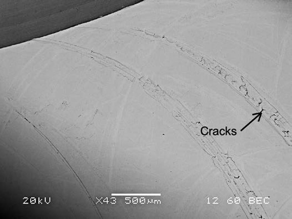
Figure 16—BSE image of Figure 15.
Description of Figure 16
BSE images can easily detect foreign particles that may be embedded in a surface. Some common types of particles include grinding dust (such as aluminum oxide, cubic boron nitride, or silicon carbide), or environmental dust like silica sand. BSE images can distinguish between different elemental compositions based on their atomic weight. In a BSE image, aluminum and silicon appear dark as they have low atomic numbers of 13 and 14 respectively, while iron, which has a relatively high atomic number of 26, appears bright. By examining Figure 16, one can see that there are no dark particles present, indicating that there are no hard, foreign particles embedded in the roller end. Therefore, the abradants are likely to be debris particles from micropitting and macropitting of the bearing components that have been work-hardened by overrolling.
BSE images can aid in detecting cracks because carbon from hydrocarbon lubricant gets trapped within the cracks, making them appear dark in BSE images. Figure 16 displays multiple cracks within two broad grooves. It's worth noting that these cracks are not noticeable in the SEM image shown in Figure 15.
Figure 17 is an SEM image of the roller end within the area of the rectangle in Figure 15 at higher magnification.
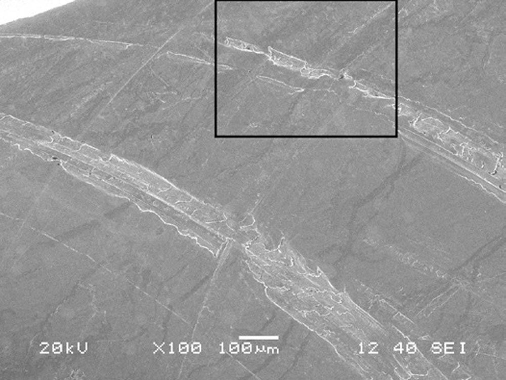
Figure 17—SEM image of roller end at higher magnification.
Description of Figure 17
The image displays the rough surfaces inside the grooves, with plastic material flowing into them due to intersecting scratches. See Figure 18 for an enlarged view of the area within the rectangle.
Figure 18 is an SEM image of the roller end within the area of the rectangle in Figure 17 at higher magnification.
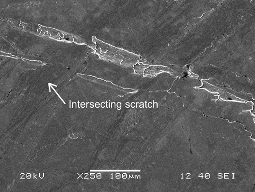
Figure 18—SEM image of roller end at higher magnification.
Description of Figure 18
The upper rough groove is the groove labeled 3 in Figure 15. The lower smooth groove is a scratch that was interrupted by plastic deformation caused by intersecting scratches.
Figure 19 is an SEM image of the roller end at another area.
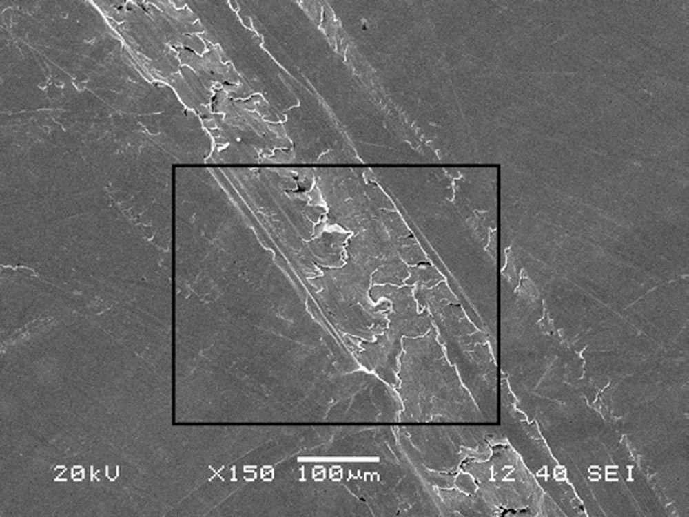
Figure 19—SEM image of roller end at higher magnification.
Description of Figure 19
This image shows a wide groove with flattened platelets due to plastic deformation in the groove, cracks on the upper shoulder, and plastic flow on the lower shoulder caused by intersecting scratches. See Figure 20 for an enlarged view of the area within the rectangle.
Figure 20 is an SEM of the roller end within the area of the rectangle in Figure 19 at higher magnification.
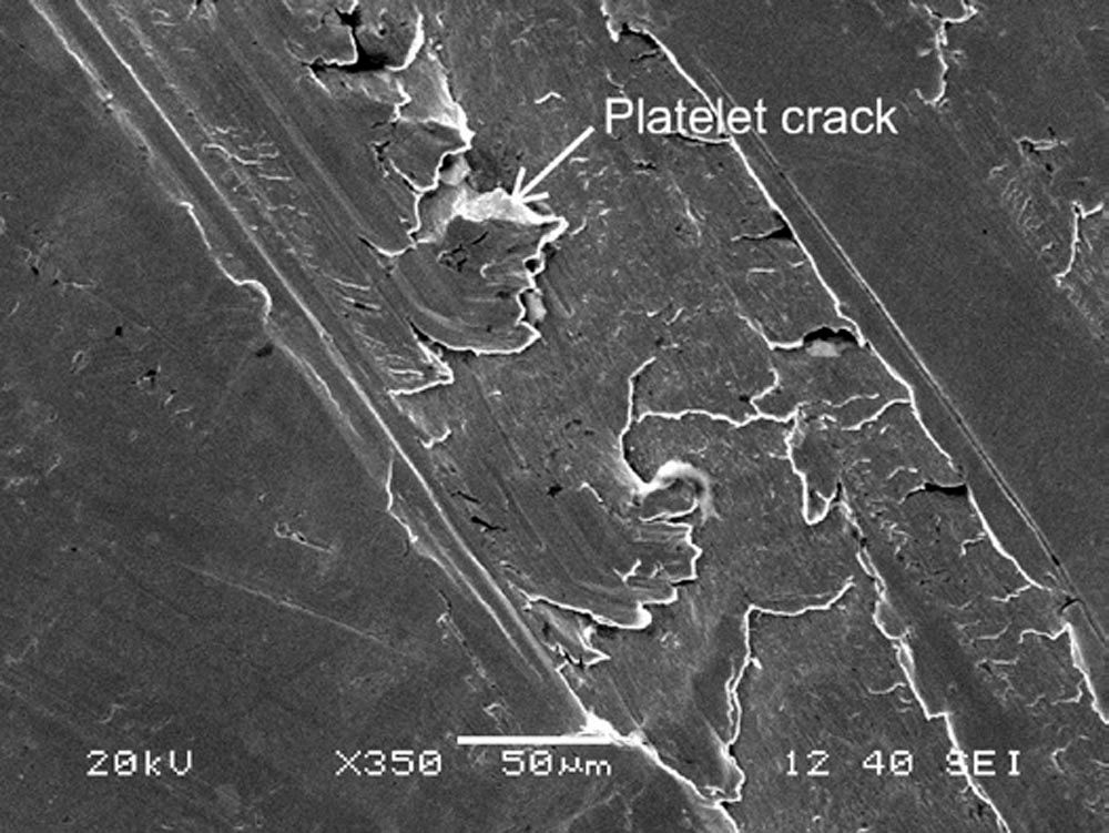
Figure 20—SEM image of the roller end at higher magnification.
Description of Figure 20
Grooving abrasion creates raised shoulders on both edges of the grooves. When the raised shoulders encounter a mating surface, they get flattened, which we call ironing. As the roller rotates, it causes angular displacement and cracking of the thin platelets of plastically deformed surface material.
Figures 15–20 demonstrate that the shape of grooving abrasion in wide grooves is consistent with a process of plastic deformation that leads to the formation of thin platelets of material flow. These platelets are likely to contain cracks caused by tensile stress due to frictional force between the roller and a fixed particle on the IR thrust rib. It is probable that the wide groove width, which can be up to 400 µm, is produced by macropitting debris.
SEM and BSE Images of Thrust Rib Wear
The following Figures 21–29 are SEM and BSE images of the wear on the IR thrust rib.
Figure 21 is a BSE image of the IR thrust rib within the area of the rectangle in Figure 5 at higher magnification.
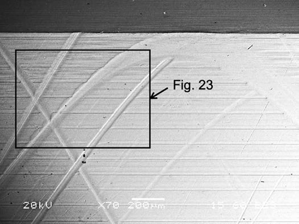
Figure 21—BSE image of the IR thrust rib.
Description of Figure 21
In the image, the top part shows the undercut of the grinding relief. The horizontal grooves that can be seen are a natural part of the surface topography that was created by grinding the face of the IR thrust rib. There are also finer grinding marks on the surface between the horizontal grooves. Below the rectangle, three black dots are believed to be from a fractured hard particle, which is a rare occurrence for the images in this report. See Figure 23 for an enlarged view of the area within the rectangle.
When comparing Figures 20 and 21, the IR thrust rib in Figure 21 appears more ductile than the roller end in Figure 20 because there were no cracks in the IR thrust rib.
Figure 22 is an SEM image of Figure 21.
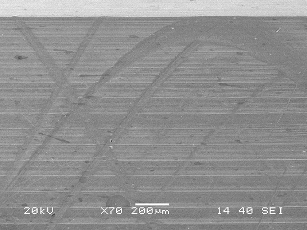
Figure 22—SEM image of the IR thrust rib.
Description of Figure 22
Comparing Figures 21 and 22, it is evident that BSE images provide a higher resolution of surface topography and are ideal for displaying grooving abrasion features compared to SEM images.
Figure 23 is a BSE image of the IR thrust rib within the area of the rectangle in Figure 21 at higher magnification.
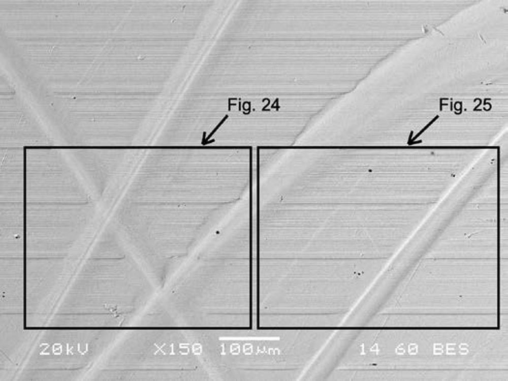
Figure 23—BSE image of the IR thrust rib at higher magnification.
Description of Figure 23
The curtate epitrochoid groove in the central part of the image displays ironing plastic deformation of the upper shoulder of the groove. The narrow groove at the right of the image has less plastic deformation of the upper shoulder. See Figure 24 for an enlarged view of the area within the left rectangle. See Figure 25 for an enlarged view of the area within the right rectangle.
Figure 24 is a BSE image of the IR thrust rib within the area of the left rectangle in Figure 23 at higher magnification.
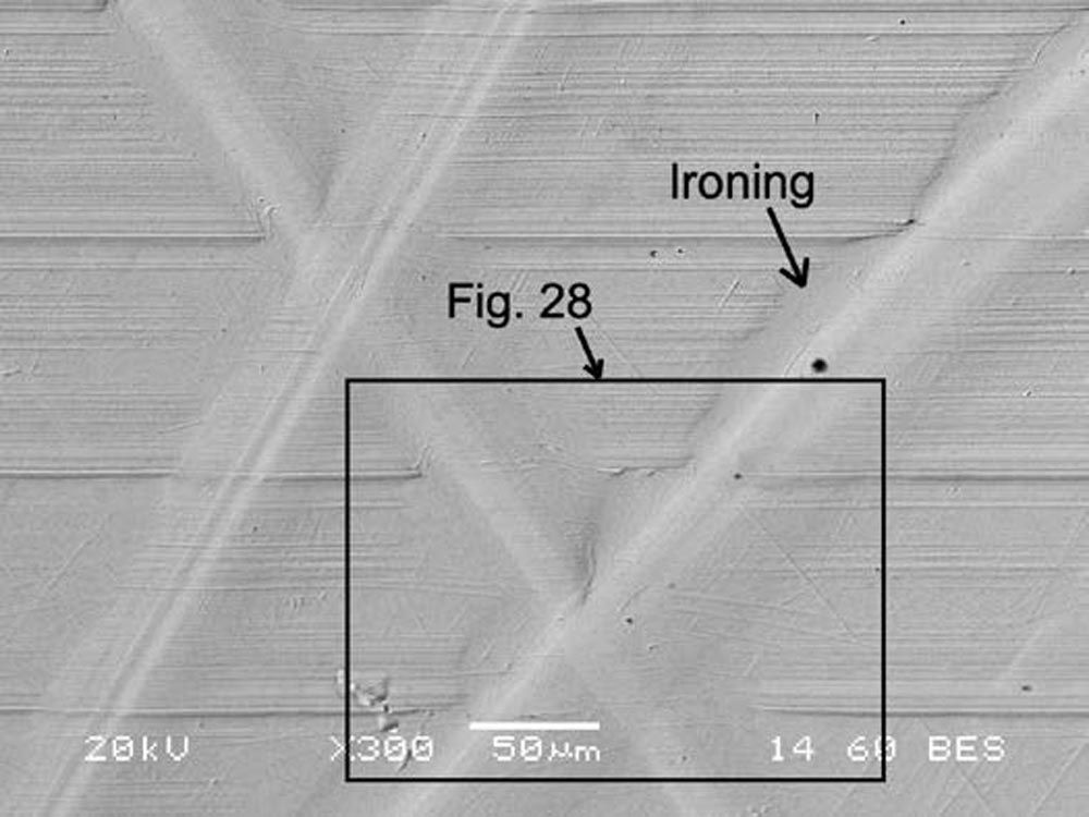
Figure 24—BSE image of the IR thrust rib at higher magnification.
Description of Figure 24
Ironing of the upper shoulder of the larger groove caused the material to flow on top of the original grinding marks on the face of the IR thrust rib. See Figure 28 for an enlarged view of the area within the rectangle.
Figure 25 is a BSE image of the IR thrust rib within the area of the right rectangle in Figure 23 at higher magnification.
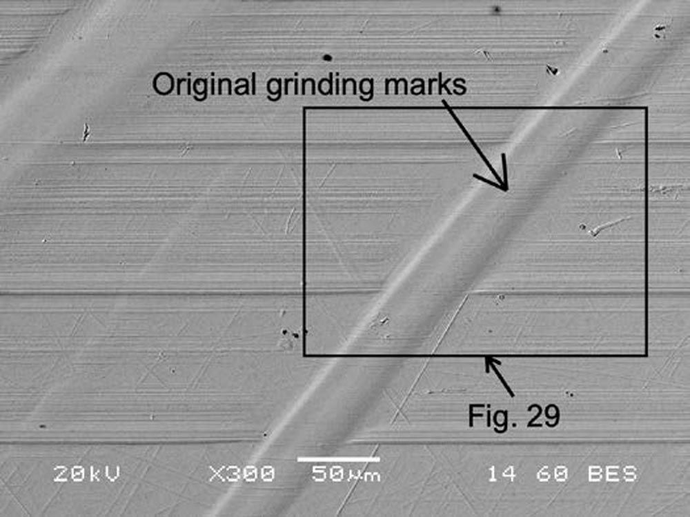
Figure 25—BSE image of the IR thrust rib at higher magnification.
Description of Figure 25
The groove on the right-hand side of the image is a common example of a narrow groove with a small upper shoulder and original grinding marks present within the groove. This shape is indicative of grooving abrasion, which occurs due to plastic deformation without any evidence of cutting abrasion. Additionally, since the width of the narrow groove is approximately 30 µm, the narrow grooves were likely produced by micropitting debris. See Figure 29 for an enlarged view of the area within the rectangle.
Figure 26 is an SEM image of Figure 25.
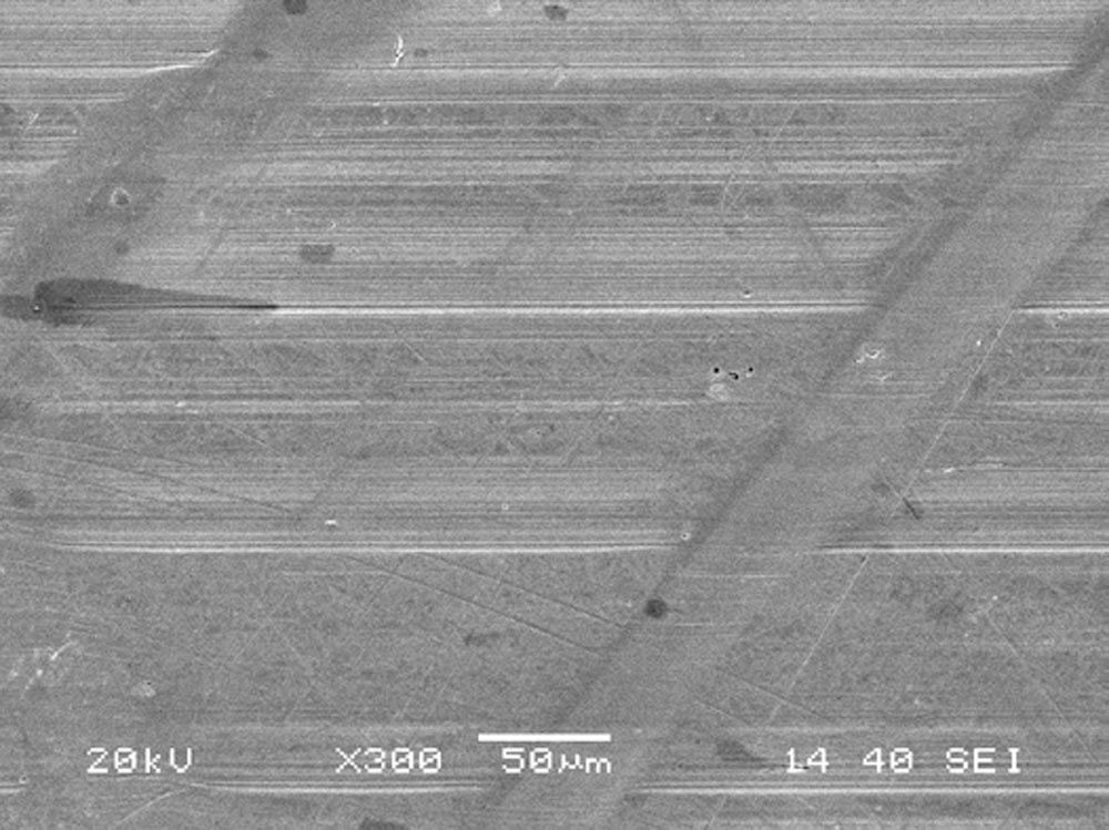
Figure 26—SEM image of Figure 25.
Description of Figure 26
In comparison to Figure 25, Figure 26 demonstrates that BSE images are ideal for displaying surface topography, while SEM images are better suited for displaying surface marks, films, and contamination. Although SEM only produces black-and-white images, when paired with energy dispersive spectroscopy (EDS), it can identify the chemical composition of surface films.
Figure 27 is an SEM image of Figure 24.
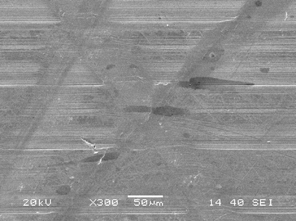
Figure 27—SEM image of Figure 24.
Description of Figure 27
Compared to Figure 24, Figure 27 shows that BSE images are best for showing surface topography, and SEM images are best for showing surface films. The black marks are artifacts created by a residual cleaning agent.
Figure 28 is a BSE image of the IR thrust rib within the area of the rectangle in Figure 24 at higher magnification.
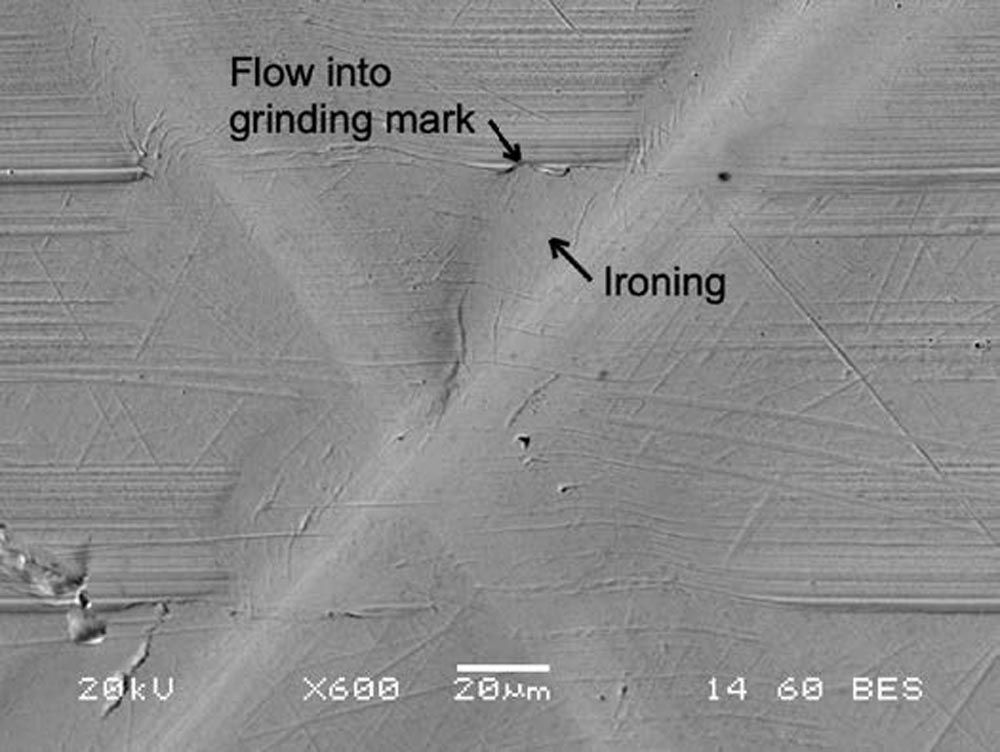
Figure 28—BSE image of the IR thrust rib at higher magnification.
Description of Figure 28
This image demonstrates an instance of plastic deformation caused by ironing the shoulders of grooving abrasion. It is apparent that the ironing process has resulted in the distortion of the original grinding marks, and in some cases, the material has flowed into sections of the deeper grinding marks.
Figure 29 is a BSE image of the IR thrust rib within the area of the rectangle in Figure 25 at higher magnification.
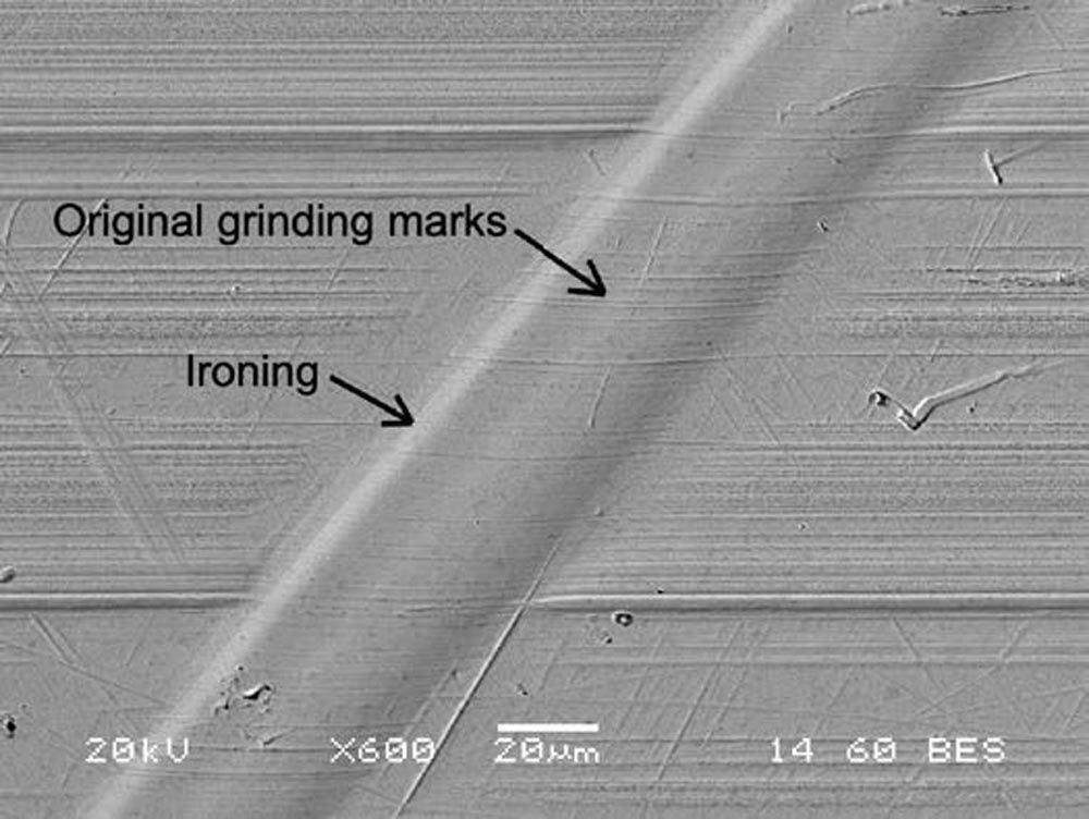
Figure 29—BSE image of the IR thrust rib at higher magnification.
Description of Figure 29
This image displays the presence of original grinding marks inside the groove. This phenomenon is quite like the circular indentation formed by a tungsten ball of a Brinell tester. When the Brinell indentation is made, plastic deformation occurs below the surface and the original grinding marks remain preserved within the indentation because the surface stays elastic.
Figures 21-29 indicate that the wide and narrow grooves on the IR thrust rib have a ductile appearance, with no signs of cracking. However, Figures 15–20 reveal that the wide grooves on the rollers display a more brittle appearance, with evidence of plastic deformation and platelet cracking. The reason for the different morphology of grooves in the rollers and IR thrust rib is not due to a variation in hardness, as the hardness of the roller was 60.8 HRC, and that of the IR thrust rib was 61.6 HRC, which is not a significant difference.
Discussion
According to Fitzsimmons and Clevenger (Ref. 2), the lubrication process of TRBs involves the entry of lubricant at the small end of the rollers. The lubricant is then pumped towards the large end of the rollers because of the taper on the rollers. This movement may cause contaminants in the lubricant to be transported to the IR thrust rib, as shown in Figure 30.
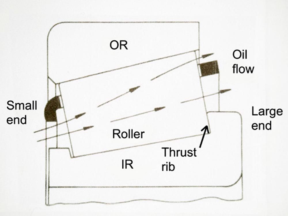
Figure 30—Lubricant flow in a TRB (Ref. 2).
To study the influence of metallic wear debris on TRBs, Fitzsimmons and Clevenger utilized particles that were typical of work-hardened bearing material with a Mohs hardness of 8. These particles were harder than carburized steel, which has a Mohs hardness of 7. They found that metallic particles ranging in size between 5–40 µm caused significant wear on both the TRB roller ends and IR thrust ribs. However, the elastohydrodynamic film thickness of the lubricant employed in their experiments was only 0.2 µm. Therefore, they concluded that the particles were significantly reduced in size as they were overrolled in contacts between the roller and the IR and OR raceways.
We found two types of wear debris - micropitting and macropitting. Micropitting debris was smaller than 10 µm, while macropitting debris was around ten times larger. Both types of debris were ductile and could be flattened, indicating they were hard but ductile.
Abradants experience a force normal to the groove plane, and a tangential force tangent to the path of the epitrochoid. Particles that are around 30 µm wide undergo low normal and tangential forces. This helps the groove maintain its smoothness and reflectivity. However, larger particles are subject to higher forces, causing the grooves to widen, and resulting in rough grooves with diffuse reflection.
The SEM and BSE images showed no evidence of cutting abrasion or transferred material. We conclude that cutting abrasion and adhesion played no role in the grooving abrasion found on the roller ends or the IR thrust rib.
Conclusions
- The failure mode for roller ends and the IR thrust rib is 2-body grooving abrasion.
- Grooving abrasion created narrow grooves less than 30 µm wide and wide grooves up to 400 µm wide.
- Narrow grooves on the roller ends had smooth surfaces that exhibited specular reflection in LOM images and appeared as scratches.
- Thin platelets of plastically deformed and cracked material on roller ends created wide grooves with rough surfaces. These grooves exhibited diffuse reflection in LOM images and appeared as frosted grooves.
- Narrow grooves were probably caused by small, work-hardened particles from micropitting debris. Despite being about 30 µm wide, these narrow grooves could have been created by much smaller particles that were elongated by overrolling.
- Wide grooves were probably caused by large, work-hardened particles from macropitting debris.
- Particles creating narrow grooves experienced relatively small normal and tangential forces, which caused smooth grooves and specular reflection.
- Particles creating wide grooves experienced relatively large normal and tangential forces, which caused rough grooves and diffuse reflection.
- Roller end grooving abrasion followed prolate epitrochoid paths created by particles fixed on the IR thrust face.
- IR thrust rib grooving abrasion followed curate epitrochoid paths created by particles fixed on roller ends.
- No evidence of embedded foreign particles was found in any image associated with grooving abrasion.
- No evidence of micropitting or macropitting fixed debris was found in any image. This indicates that only temporarily fixed debris created 2-body grooving abrasion.
- Wide and narrow grooves on the IR thrust rib appeared ductile, while wide grooves on roller ends showed more brittle plastic deformation and platelet cracking. The different morphology is not due to hardness variation. Roller hardness was 60.8 HRC, and IR thrust rib hardness was 61.6 HRC, which is not significantly different.
- IR thrust rib groove abrasion showed original grinding marks in narrow grooves, and ironing on the shoulders of wide grooves, indicating ductile deformation.
- Cutting abrasion and adhesion played no role in the grooving abrasion found on the roller ends and the IR thrust rib.
- BSE images are ideal for showing surface topography, while SEM images are better at displaying surface films.
Annex A
Epitrochoids
Figures A1 and A2 were produced by the Desmos graphing calculator available at the following links:
Link for Figure A1: desmos.com/calculator/fy72awovzl
Input data for Figure A1:
a = 51 (number of rotations of rolling circle r)
R = 16.54 (Rroller)
r = 280 (Rraceway)
d = 282.5 (distance of generating point from the center of rolling circle r)
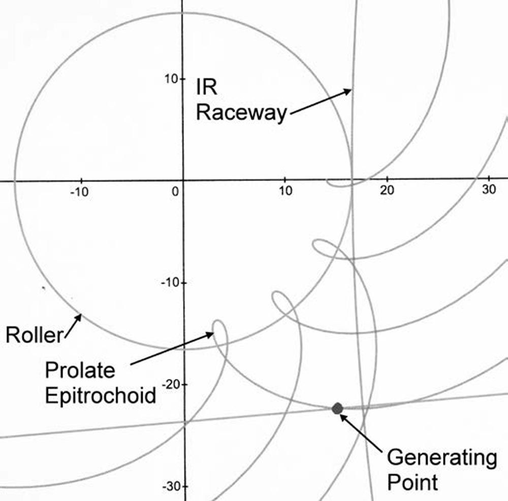
Figure A1—Prolate Epitrochoid.
Link for Figure A2: desmos.com/calculator/ug0hdi91w1
Input data for Figure A2:
a = 1.5 (number of rotations of rolling circle r)
R = 280 (Rraceway)
r = 16.54 (Rroller)
d = 13 (distance of generating point from the center of rolling circle r)
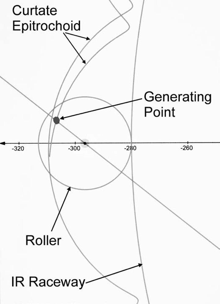
Figure A2—Curtate Epitrochoid.
Definitions
Rroller = radius of the large end of the TRB roller
Rraceway = radius of the large end of the TRB IR raceway
Epitrochoid: A geometric curve traced by a fixed point on a rolling circle that rolls around the perimeter of another fixed circle.
Curtate Epitrochoid: occurs when the fixed point on the rolling circle is inside the rolling circle.
Prolate Epitrochoid: occurs when the fixed point on the rolling circle is outside the rolling circle.

References
- Blau, P.J., “Tribosystem Analysis- A Practical Approach to the Diagnosis of Wear Problems,” CRC Press, 2016; pp. 1–192.
- Fitzsimmons, B., and Clevenger, H.D., “Contaminated Lubricants and Tapered Roller Bearing Wear,” ASLE Trans., Vol 20, No. 2, 1977; pp. 97–107. https://doi.org/10.1080/05698197708982822
- Errichello, R.L., “Morphology of Micropitting,” AGMA Technical Paper 11FTM17, 2011; pp. 1–19.
