
(1)
υt= plunge feedrate (mm/min)
φs=grinding wheel profile angle (deg)
b=gear face width (mm)
βm=gear mean spiral angle (deg)
Number of Rotations
For higher precision gears, or gears with a large amount of grinding stock, multiple grinding passes around the gear may be necessary to meet the required quality. However, for most applications, one rotation of the gear is sufficient with plunge grinding.
Plunge Grinding Positions
Plunge grinding positions will depend on the amount of incoming stock and heat treat distortion of the gear. To avoid excessive grinding wheel wear, the grinding wheel should not contact the gear during the first position.
Dwell Time
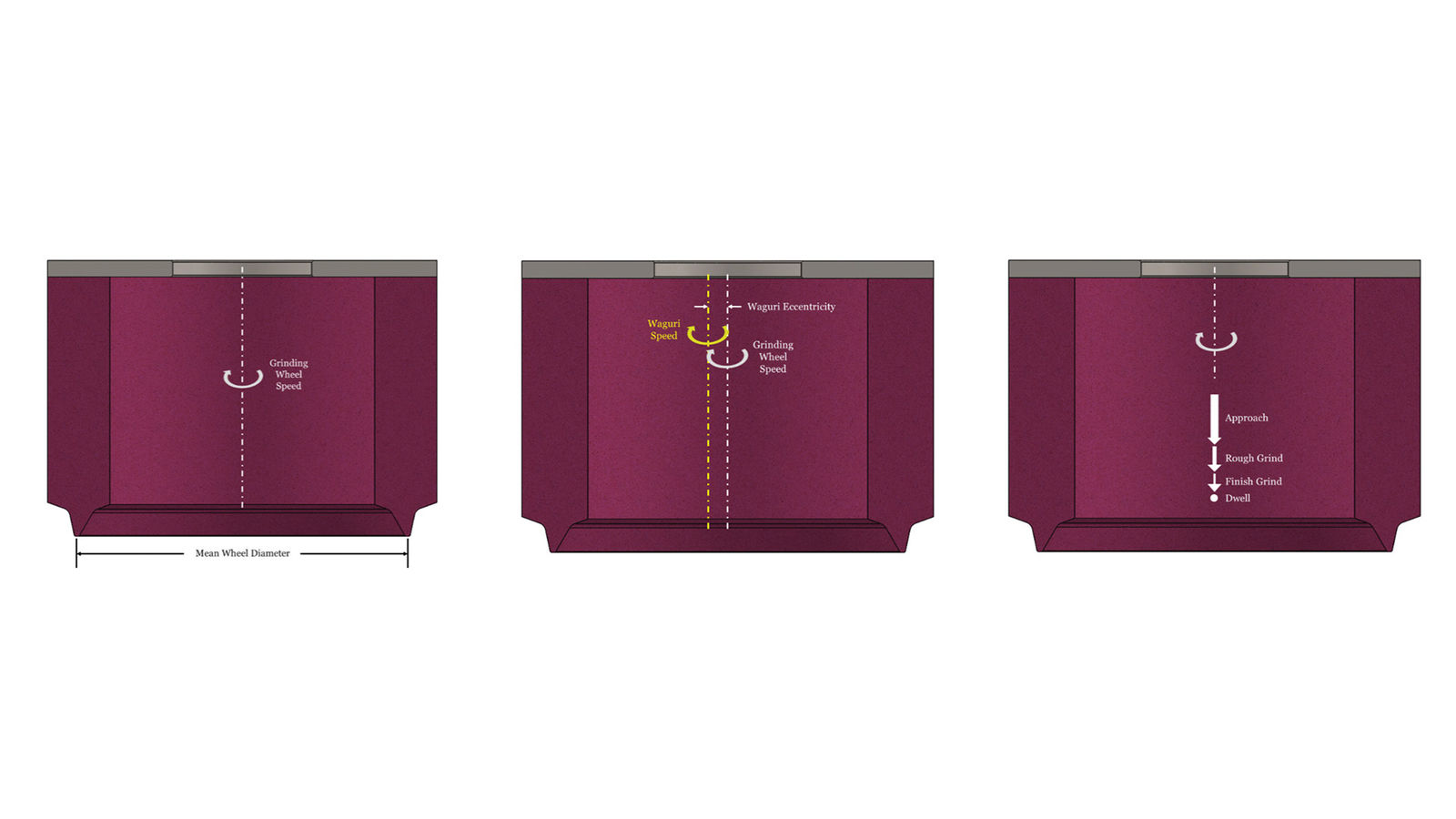
The dwell takes place at the end of each plunging cycle and allows the entire grinding system to return to its normal state. The workpiece and grinding machine will deflect during the grinding cycle, like a spring being compressed, and the dwell time allows that spring to return to its normal state. It also has the added benefit of reducing the surface finish. Dwell time typically ranges from 0.1 to 0.4 seconds, or at least 6 to 8 revolutions of the Waguri spindle.
Generating Grinding Parameters
Grinding Wheel Speed
Grinding wheel speed with generating grinding cycles, as with plunge grinding cycles, is typically in the range of 23-25 m/s. Similar to plunge grinding, there is a careful balance between wheel wear, surface finish, and grinding temperatures that must be considered when selecting a grinding wheel speed.
Grinding Passes
Like plunge grinding, one grinding pass (“single roll”) is sufficient for generating grinding, however, there are some circumstances where two passes (“double roll”) are necessary. Double roll grinding consists of splitting the grinding stock into two parts and performing a grinding pass in one direction along the tooth, then reversing the grinding direction to grind the remaining stock.
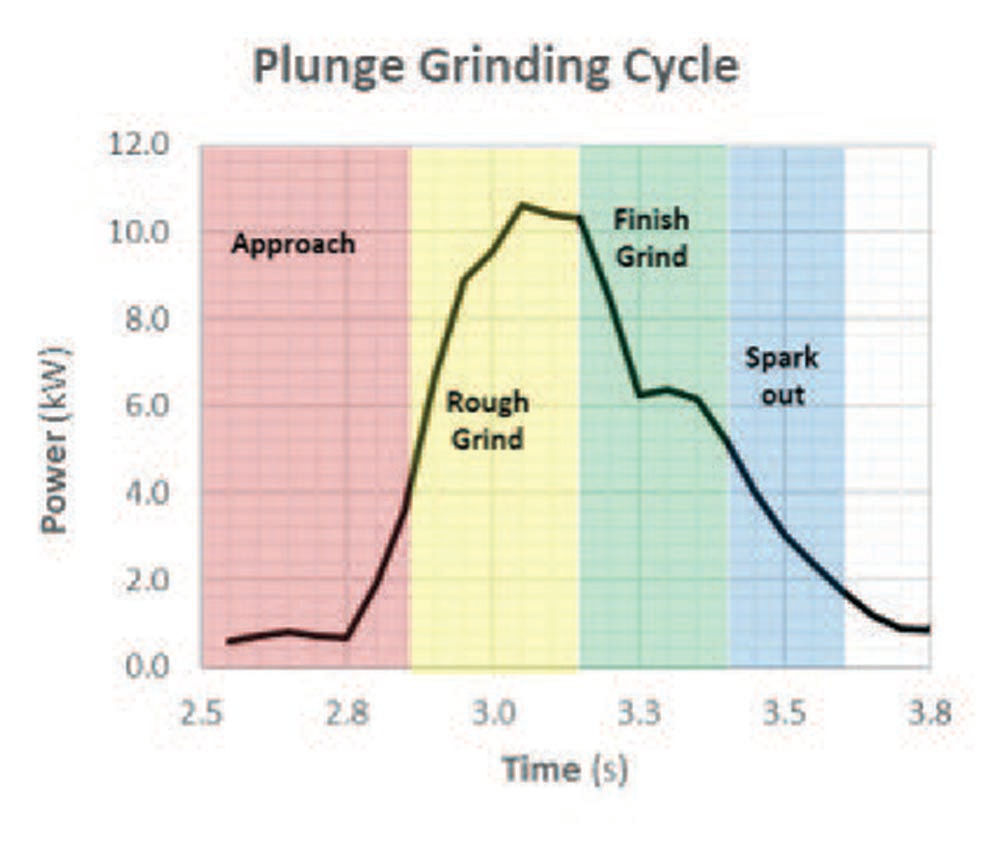
Figure 4—Example grinding cycle spindle power.
Generating Feed Rate
The feed rate for generating grinding is programmed in degrees of roll per second. This feed rate is selected based on the calculated specific material removal rate, for which 4.0mm2/s is a conservative starting point. The calculation for generating grinding Q’ is shown in Equation 2:

(2)
υw= generating feedrate (deg/s)
b=gear face width (mm)
∆s=stock amount normal to flank (mm)
∆α=generating interval-can assume 30° (deg)
βm=gear mean spiral angle (deg)
Part 2: Grinding Wheel Selection
The selection of the grinding wheel will depend on the module of the gear to the ground, the material and hardness of the gear, and the desired surface finish. A vitrified grinding wheel consists of three main parts: abrasive, bond, and air (porosity). A careful balance is needed between these three variables, and that is controlled by the wheel specification which should be carefully matched to application requirements.
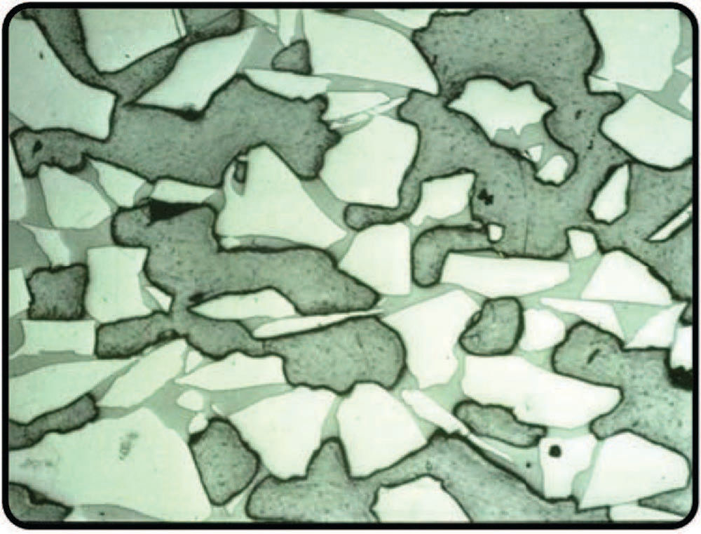
Figure 5—Grinding wheel cross-section.
Abrasive Types
The main types of abrasive used in bevel gear grinding are conventional aluminum oxides, and sintered aluminum oxides, also known as ceramics. Modern bevel gear grinding wheels are all either a blend of ceramic and conventional aluminum oxide, or 100 percent ceramic. Ceramic abrasive is expensive to manufacture, so 100 percent ceramic wheels are less common and typically limited to high material removal rate applications such as when grinding from solid.
Norton | Saint-Goban Abrasives offers several types of ceramic abrasives for bevel gear grinding including Quantum Prime which is a sharp, angular ceramic grain, and TQ which is a shaped extruded ceramic grain. Images of both grain types are shown in Figure 6.
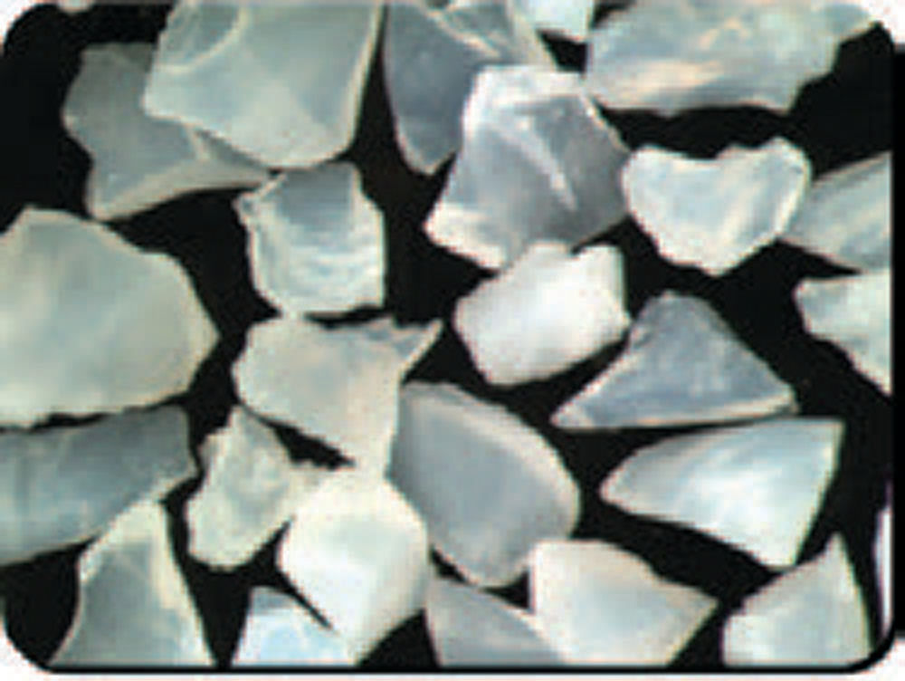
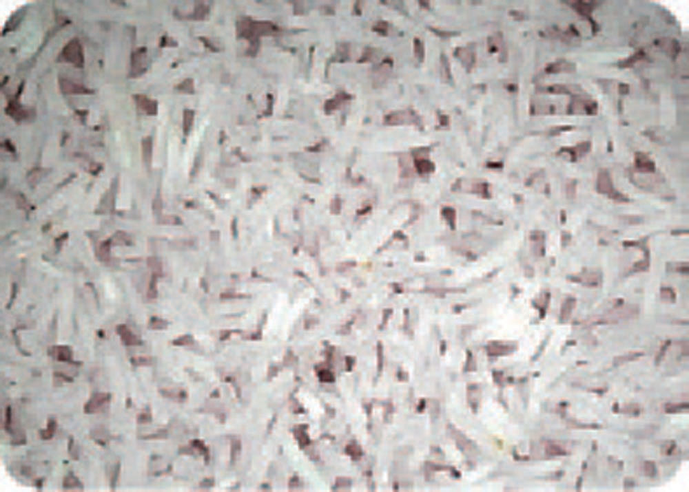
Figure 6—Norton angular and extruded ceramic grains.
Grit Size
Grit size is the size of the abrasive in the grinding wheel, represented as a mesh size. The higher the grit mesh size, the smaller the abrasive. For most automotive or industrial bevel gear applications, an 80-grit size is adequate to achieve the required surface finish and tip geometry. For finer-pitched gears, a finer mesh size (100, 120, or 150) would be used to improve tip form holding. For grinding gears from solid, a coarser mesh size may be used, likely 60 grit.
Wheel Grade
The grade, or hardness of the grinding wheel represents the amount of bond that is present in the grinding wheel. The ideal amount of bond retains a sharp grit as long as possible and releases it when the grit becomes dull. The addition of more bond in a grinding wheel can increase its strength and reduce wheel wear but can also cause higher grinding temperatures due to friction interaction between the bond and workpiece, as well as from holding on to dull grits for too long. Similarly, not enough bond in the wheel can result in the bond releasing sharp grits too early, resulting in high wheel wear.
Structure
The structure represents the amount of abrasive in the grinding wheel. This directly impacts the spacing between the abrasive grains, which—when too close together—can cause workpiece chips to get stuck in the grinding wheel. If there is not enough abrasive in the wheel, this can also increase wheel wear. Lower structure numbers mean there are more abrasives closely spaced together, whereas higher structure numbers mean there are fewer abrasives spaced further apart.
Bond Type
Vitrified grinding wheel bonds are primarily glass, but different characteristics of the bond can be modified to provide better retention of the abrasive grain with a smaller amount of bond. Still, even with a very strong bond and a low bond amount, some interaction between the grinding wheel bond and workpiece results in rubbing and heat. This heat both increases grinding temperatures and weakens the bond itself. After all, the glass will soften as it heats, which can reduce its ability to retain abrasive.
The newest Norton bond system for gear grinding, VS3PN, provides a solution to this problem by giving the bond itself the ability to remove material from the workpiece. This reduces heat generation from bond rubbing, which not only reduces grinding temperatures but also strengthens the bond.
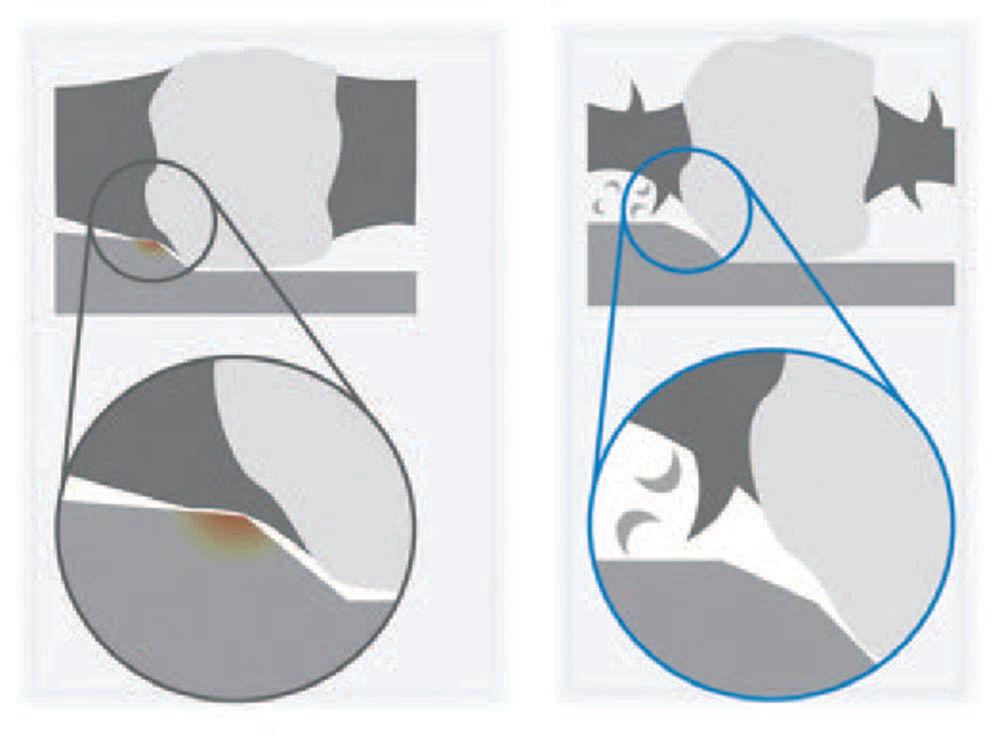
Figure 7—Standard bond (left) vs. Next Generation VS3PN Norton Bond (right).
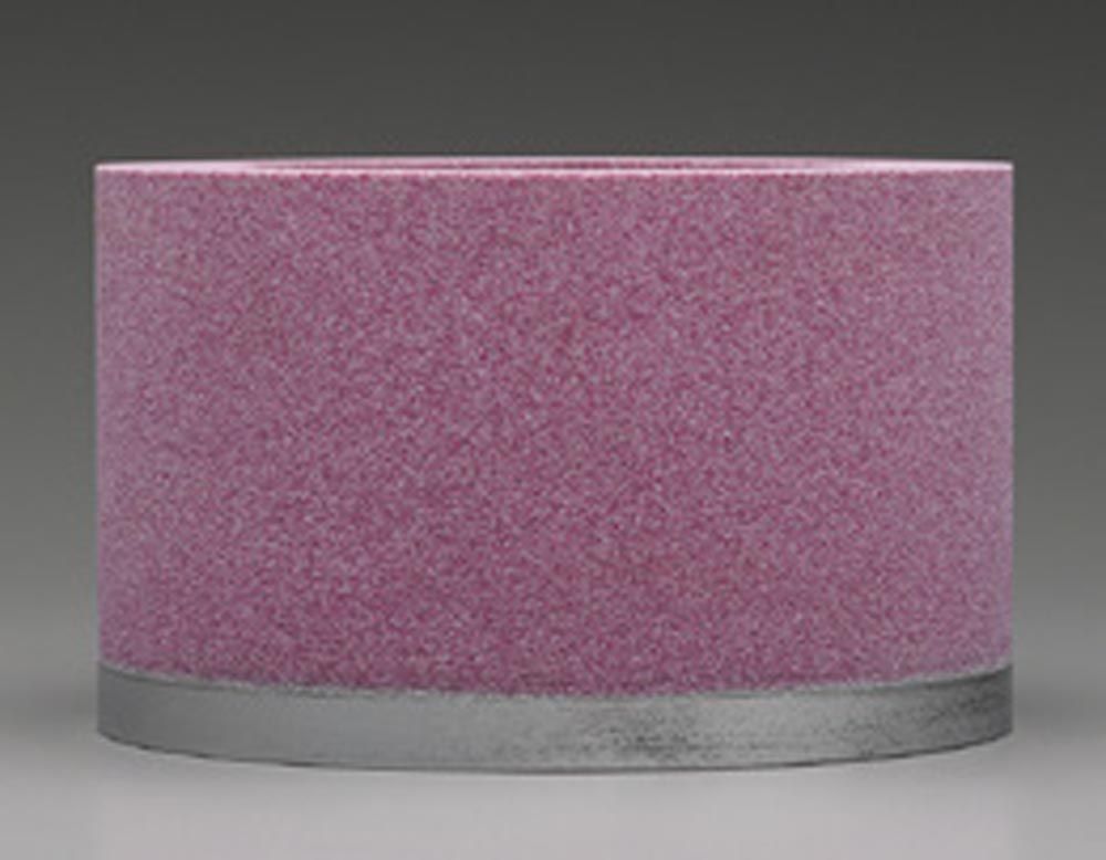
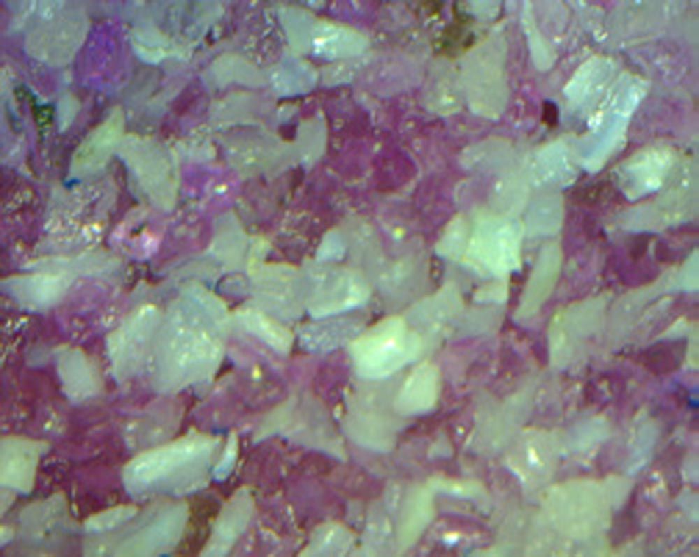
Figure 8—Norton WGNC grinding wheel (left) and grain micro view (right).
Recommended Specification for Small to Medium Bevel Gears (Module
For small to medium-sized bevel gears, we recommend using the Norton WGNC grinding wheel specification. This specification uses the Norton VS3PN bond system paired with a blend of ceramic grain and premium aluminum oxide grain. The bond and structure have been optimized specifically for bevel gear grinding to provide an excellent balance of low grinding temperatures and long grinding wheel life. For example, see Figure 9 for the good quality results that can be achieved when using this grinding wheel.
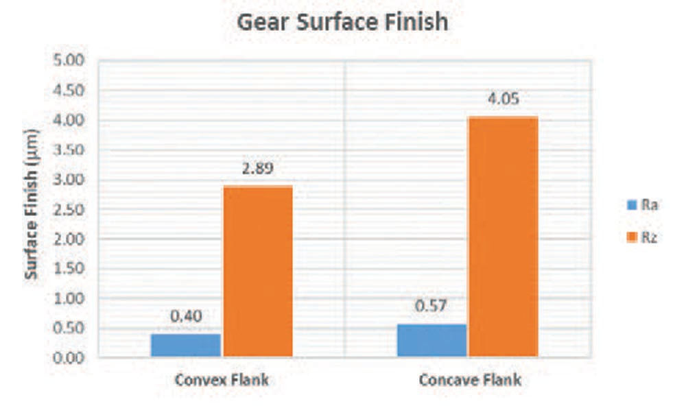
Figure 9—WGNC surface finish.
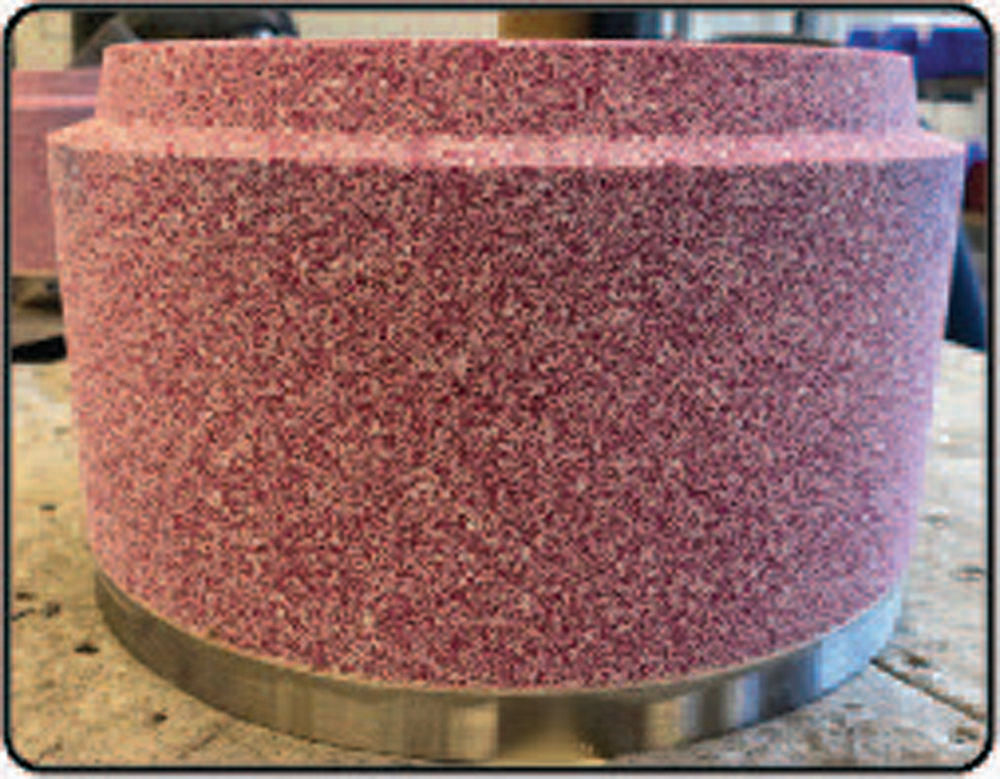
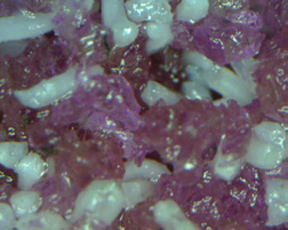
Figure 10—Norton WGRC grinding wheel (left) and grain micro view (right).
Recommended Specification for Large Bevel Gears (Module > 7.5)
For larger bevel gears, we recommend using the Norton WGRC grinding wheel specification. Like the WGNC specification, WGRC uses the VS3PN bond system paired with a blend of shaped extruded ceramic grain and premium aluminum oxide grain. See Figure 11 for examples of the surface finish that can be achieved.
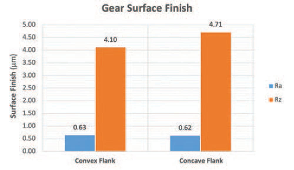
Figure 11—WGRC surface finish.
Recommended Specification for Grinding from Solid
Grinding bevel gears from solid is becoming more popular, especially for prototyping or for low volume product runs. When grinding bevel gears from the solid, manufacturers can avoid the additional expense of purchasing complex cutting tools which may have a long delivery time, and sometimes even avoid purchasing an additional machine.
New advancements
Extruded ceramic grains, TG2 and TQX, excel at grinding from solid. Running a 100 percent TG2 or TQX grinding wheel will offer the highest performance, while blended ceramic grinding wheels provide a more economical option. Grinding wheels comprised of 100 percent TG2 and TQX have the added benefit of a higher natural porosity that occurs from packing the grains together with a longer aspect ratio as shown in Figure 12.
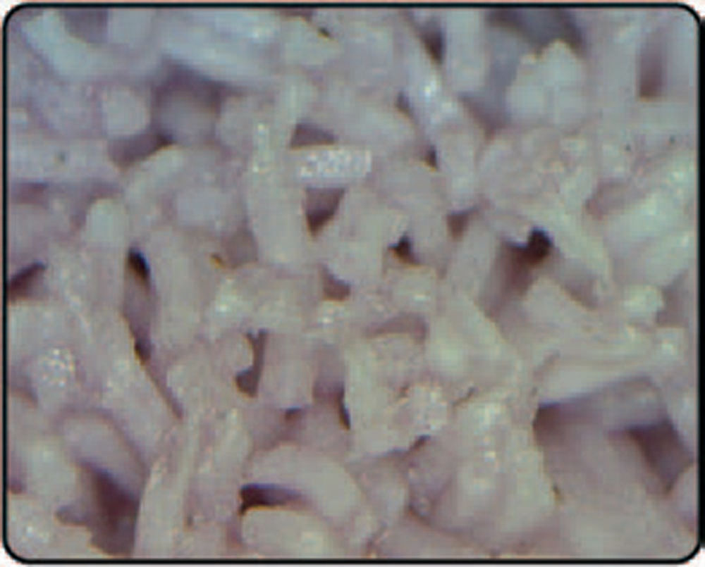
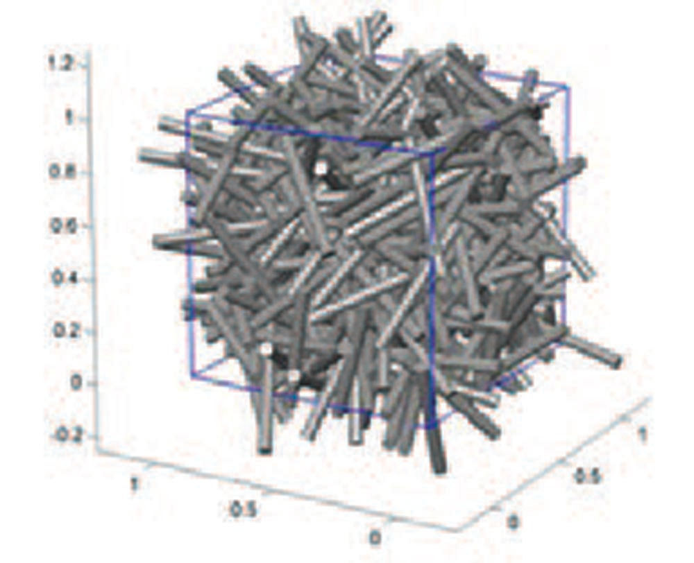
Figure 12—TG2/TQX grain image and packing density (Ref. 1).
Part 3: Dressing Parameter Selection
Equally as important as grinding parameters are the dressing parameters of the grinding wheel. This has a direct impact on the resulting surface finish of the grinding wheel and the waviness of the flanks. Here are the main parameters to consider regarding the dressing cycle:
Dressing Depth
Dressing depth is the amount of material removed from the grinding wheel during the dressing cycle. Higher dressing depths will result in higher surface finish and higher dresser wear. It’s very important to take the flank angles of the grinding wheel into account, as the dressing amount will vary widely from the root and inner flank to the outer flank.
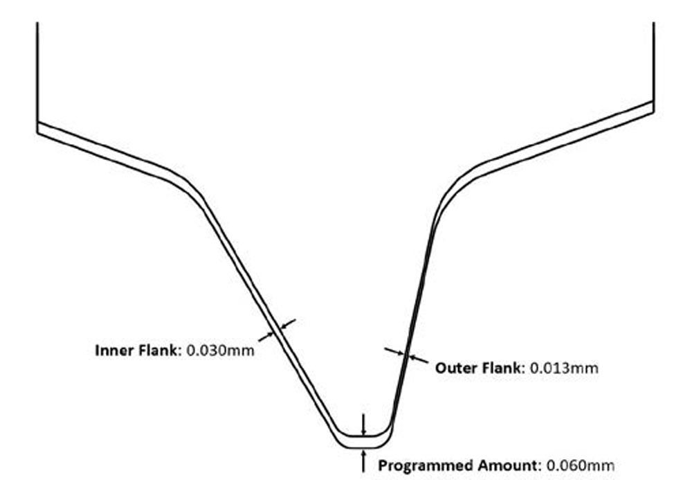
Figure 13—Dressing depth vs. profile angle.
Equation 3 is for equivalent dressing depth:

(3)
aed=equivalent dressing depth (mm)
ad=dressing depth (mm)
 s=grinding wheel profile angle (deg)
Dressing Velocity Ratio
The dressing velocity ratio (see Equation 4) is the ratio of the dresser surface velocity versus the grinding wheel velocity. Lower velocity ratios will result in lower surface finish and higher grinding forces/temperature, while higher velocity ratios will give higher surface finish and lower grinding forces/temperature. The charts shown below are from an excellent thesis by Nicole Weßels at RWTH Aachen University in 2009, showing the relationship between dressing parameters on surface finish and grinding spindle load.

(4)
qd=dressing velocity ratio
υs=grinding wheel velocity (m/s)
υd=dresser velocity (m/s)
 Figure 14—Dressing depth and velocity ratio vs. surface finish—convex flank (Ref. 2).
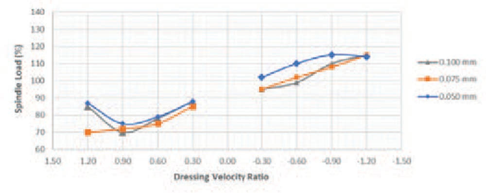
Figure 15—Dressing depth and velocity ratio vs. grinding spindle load (Ref. 2).
Dressing Overlap
The dressing overlap (see Equation 5) represents the number of times the dresser contacts a single point on the grinding wheel. For example, an overlap ratio of 2 means the dresser contacts the grinding wheel at one point exactly twice. Lower overlap values result in lower surface finish and lower waviness, while higher overlap values give higher surface finish and higher waviness.
Dressing lead is one of the variables used to calculate dressing overlap. Think of it as programming a feed rate on a lathe, in millimeters of feed per revolution, except in the case of dressing lead the measurement is millimeters of feed per revolution of the grinding wheel rather than per revolution of the workpiece. As the dresser is fed across the grinding wheel, a “thread” pattern is created, and both the feed rate and dressing depth affect the resulting surface finish.


(5)
ud=dressing overlap ratio
apd=effective dresser contact width (mm)
sd=dressing lead (mm/rev)
bd=dresser contact width (mm)
pr=dresser tip radius (mm)
ad=dressing depth (mm)
 s=grinding wheel profile angle (deg)
vfd=dressing feedrate (mm/min)
ns=grinding wheel speed (rpm)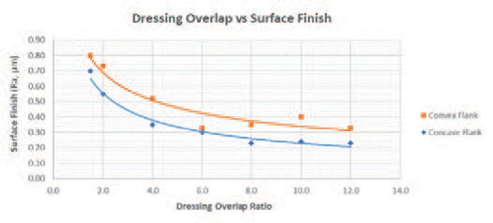
Figure 16—Dressing overlap vs. surface finish (Ref. 2).

Figure 17—Dressing depth and overlap ratio vs. grinding spindle load (Ref. 2).
Dressing Interval
The dressing interval is the number of parts that can be ground before dressing the grinding wheel. The setting will depend largely on the aggressiveness of the grinding parameters, and the volume of material that will need to be removed. Typically, larger module gears will require a lower (more frequent) dressing interval than smaller module gears, but this is not always the case. The dressing interval can vary widely, anywhere in the range of 1 – 20 parts per dress!
Part 4: Dresser Selection
The dresser geometry, diamond type, and bond type must be considered carefully for each application. The resulting geometry and surface condition of the grinding wheel are influenced by several different factors that are listed as follows, the first being the diamond type.
Natural Diamond
Natural diamonds are typically very hard, but since they are formed in nature, they can have flaws which if large enough, can impact the resulting wheel surface. Natural diamonds are not as tough as synthetic diamonds, so they are susceptible to fracturing under abusive dressing conditions.
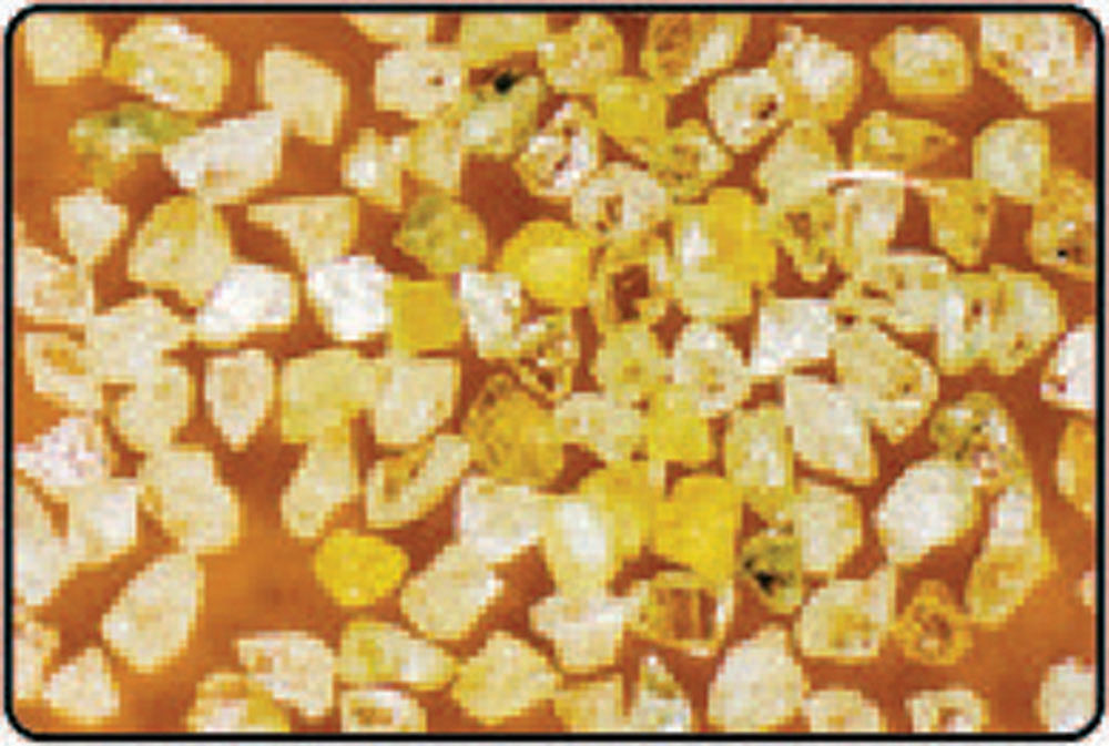
Figure 18—Natural diamonds.
CVD
CVD is a type of synthetic diamond created by a chemical vapor deposition process. CVD is tougher than natural diamonds and is the better option for dressing grinding wheels with ceramic abrasives, as they are more resilient to impact and have fewer flaws than natural diamonds.
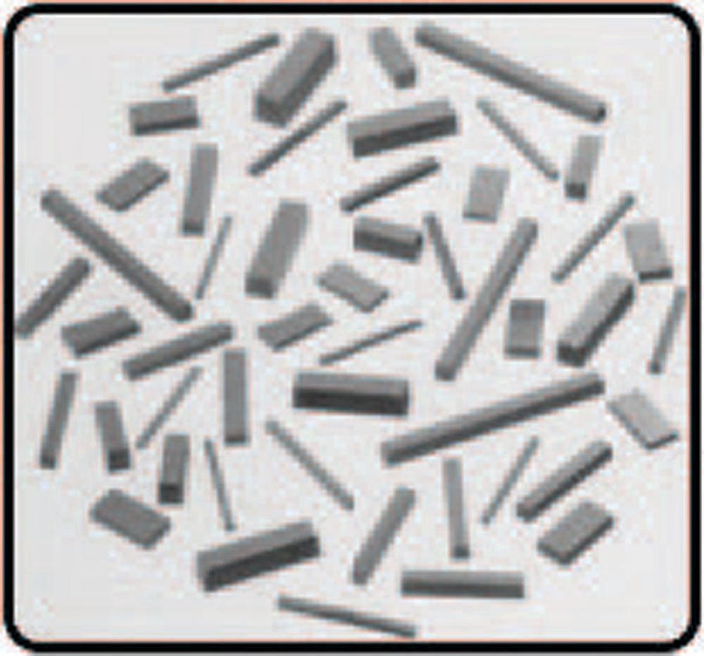
Figure 19—CVD diamond segments.
Dresser Tip Radius
Just like in turning operations on a lathe, the tip radius of the diamond directly impacts how quickly you can feed across the surface of the grinding wheel. In general, a larger dresser tip radius can feed faster across the grinding wheel and have a slower wear rate, but sometimes a larger dresser radius is not feasible due to the dressed profile geometry of the grinding wheel.
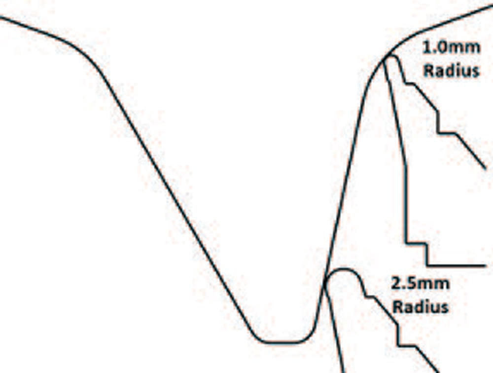
Figure 20—Dresser tip radius comparison.
CVD Segment Size
CVD segments come in many different sizes. The surface area of the CVD segment that is in contact with the dresser bond directly impacts the “gripping” strength that the bond has on the CVD segment. If the surface area of the CVD segment is too small, the segment can potentially pop out of the bond, causing surface finish, or NVH issues on the gear. Norton recommends using a large CVD segment to allow for a strong bond.
CVD Segment Pitch
The spacing between the CVD segments, or pitch, can also affect the resulting finish and waviness of the gear flank. Like a milling cutter, CVD segments that are spaced closer together (higher number of cutting edges) will give a smoother finish, and potentially a longer dresser life. While such results are usually desirable, a fine CVD segment pitch can sometimes have a negative impact on the sharpness of the grinding wheel. When selecting a CVD segment pitch, you must always consider the careful balance between wheel sharpness, dresser wear, and gear surface finish.
There are different types of bonding systems available for bevel gear dressers including the most common examples listed here:
Electroplated Bond
An electroplated bond is a layer of nickel that is deposited onto the dresser while the diamonds are tacked to the dresser steel core, creating a mechanical bond. Electroplated dressers typically use smaller mesh natural diamonds as compared to infiltrated bond dressers. The smaller diamond sizes allow for an accurate profile and low surface finish but also tend to wear quickly. The nickel bond facilitates exposure of the diamond, but it is not as strong as other bond types and is more susceptible to damage than an infiltrated dresser.
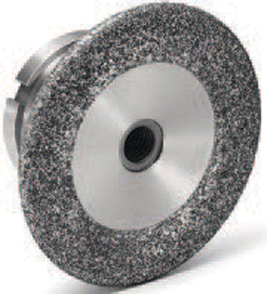
Figure 21—Electroplated dresser.
Infiltrated Bond
Infiltrated dressers use a very tough tungsten/bronze matrix to retain the diamond. Infiltrated dressers can use natural diamond or CVD and can typically handle abuse much better than electroplated dressers. When using grinding wheels with ceramic abrasive, an infiltrated dresser bond is recommended.
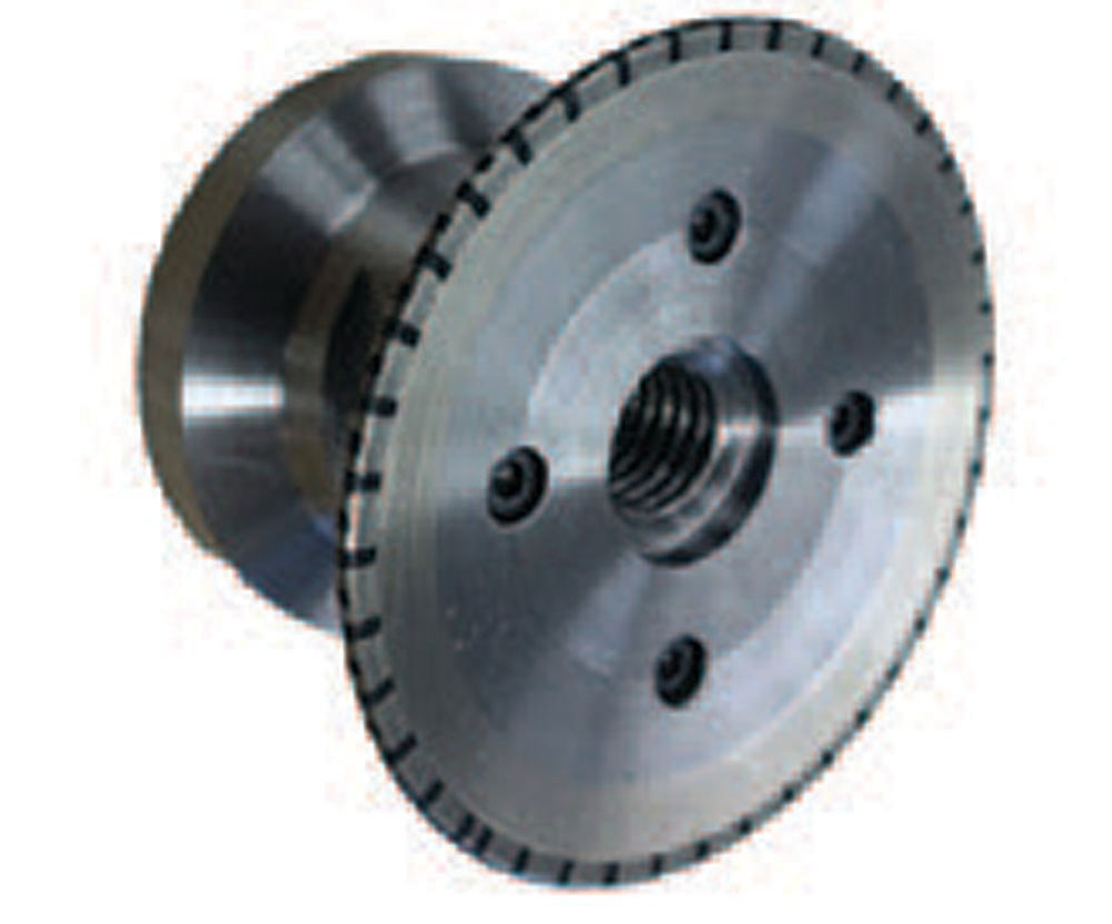
Figure 22—Infiltrated CVD dresser.
Summary
If you would like a prebuilt Excel spreadsheet to calculate bevel gear grinding and dressing parameters, reach out to Spencer Artz at Spencer.L.Artz@Saint-Gobain.com for more information.
nortonabrasives.com
References
- W. Zhang “Experimental and computational analysis of random cylinder packings with applications” Ph.D. Diss. Louisiana State University 2006
- Weßels, N.: Flexibles Kegelradschleifen mit Korund in variantenreicher Fertigung. Diss. RWTH Aachen University, 2009.





 s=grinding wheel profile angle (deg)


