Beautiful on the Inside
Higher Quality Internal Gears
Automotive gear manufacturers have implemented significant improvements in external planetary gear manufacturing yielding quieter gears. In addition, process stability has increased due to the post-heat treatment finishing processes employed.Beyond planetary pinions and sun gears, external transfer and final drive gears are commonly ground or honed, or in some cases, ground and honed. Add to this the widespread use of low pressure or “vacuum carburizing”, the current bill of process for automotive gears bears little resemblance to the hob and shave pre-heat treat processes of 20 years ago. As hybrid and electric vehicles are developed and brought to market, the demand for quieter gears continues to rise. In planetary gear systems, the internal ring gear is the final frontier for improvement to meet the requirement for quieter transmissions. This article explains various complete solutions for cutting and finishing internal ring gears.Three Ways of Creating the Teeth in Internal Gears
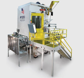
The three commonly used methods of cutting internal gear teeth each have benefits and a place in the gear manufacturing world: shaping, broaching and gear skiving/Super Skiving. There have been few revolutions in the slow evolution of the internal gear. Shaping has long been used for the production of ring gears. When helical internal broaching was developed, transmission designs changed to take advantage of this process and the huge increase in productivity. Up to 20 or more shapers were replaced by one helical broaching machine with two stations. After over 100 years of development, internal gear skiving and Super Skiving have advanced to augment, or in some cases, replace broaching. However, all three methods of internal gear production - shaping, broaching and Super Skiving – are green processes with the steel in a soft state prior to heat treatment.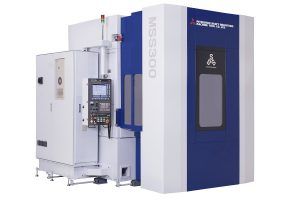
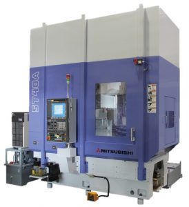
Shaping is the slowest process, with some portion of the total cycle time used in retracting the cutter to the starting position of the cutting stroke. Most modern shapers, including Mitsubishi Heavy Industries’ (MHI) ST models, use a quick return stroke to minimize this lost time.
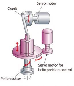
Gear skiving is faster than shaping, but slower than broaching. An advantage with this process is quick change overs for flexibility in production mix. Medium volumes are well suited for this process.
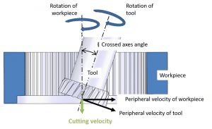
The pinion type skiving cutter operates at crossed axes with the workpiece, while rotating synchronously. This generates a sliding motion at the contact point thus creating the cutting action. However, as the cut progresses the cutting resistance increases because the angle between the rake face of the tool and the face of the workpiece becomes significantly negative (obtuse).
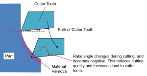
Intensive development at MHI has created simulation software that completely describes the cutting process for Super Skiving. This information creates optimal specifications for the cutting tool and cutting conditions. Multiple blade cutting tools were developed to dramatically improve tool life and reduce cycle times. The actual cutting action of the Super Skiving cutter is similar to the conventional pinion type tool. The advantage comes from the multiple blades for cutting the tooth space rather than just one cutting blade. By using a tapered roughing portion of the tool, all three blades are involved in cutting. For example, if a pinion cutter requires three cutting passes to create the gear, the super skive tool can remove the same amount of material with one pass because it has three times the number of cutting blades.
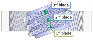
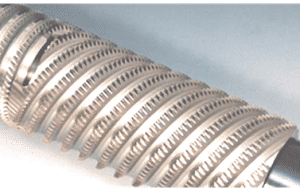
The sophisticated simulation software developed by MHI allows cutting tool engineers to understand the full effect of every tooth involved in the cut and to optimize the tool and process. Internal helical broaching is an economical choice for the highest volume mass production with minimal product mix. The process is well developed and reliable. A technological advancement in machine technology for helical broaching is the electromechanical drive system. Current, state-of-the-art broaching machines utilize electromechanical drive systems. This allows the elimination of large and inefficient hydraulic systems. In traditional hydraulic systems for helical broaching, the broach machine required a specific helical guide (lead bar) to rotate the tool during the machining stroke. The advent of electromechanical broach machines allows helical broaching without the need for the specific mechanical guides. A CNC axis controls the rotation of the tools during the broaching stroke, creating the exact helix needed. Minute adjustments are also possible and changing from one helix to another is accomplished via the CNC program and does not require any mechanical changes. Electromechanical systems use energy only when needed to produce the part. In contrast, a hydraulic system generally needs to run a large pump continuously, using prodigious amounts of electricity and creating noise and thermal pollution as well. In addition, the constant torque of the electromechanical drives produces a smoother cutting action. This can produce more consistent part quality, better surface finish on the parts, and improves tool life. Newly developed Nanodynamic coating improves broaching efficiency. The per-piece cost of consumable tooling may be cut by half, and perhaps even two thirds. Utilizing constant force tool design improves tool life and can result in a shorter tool, which in turn can reduce tool cost. Combing the advancements in broach tools with fast and rigid electromechanical machines, broaching is often the process of choice for mass production of internal helical gears.
Internal Gear Finishing After Heat Treatment
As with all steel parts, heat treatment distortion of ring gears is a fact of physics. In most typical automotive production, ring gears are cut in the green state and then heat treated without any hard finishing. Since the typical process does not finish gears after heat treatment, it is desirable to minimize distortion. To reduce distortion, many internal gears are made of semi-hardened steel and cut in this condition before heat treatment. The steel for some applications is in the range of 20-30Rc. The use of this pre-hardened steel has a negative effect on tool life for any of the cutting processes used: broaching, shaping or gear skiving. Heat treatment is often gas nitriding or ferritic nitrocarburizing, which is utilized due to the reduced distortion these processes create. From the product perspective, the resulting post nitride hardness may be acceptable, but some applications could benefit from the carburizing and hardening heat treatment process that yields 58-60Rc and increased case depth. The use of softer green steel has a beneficial effect on tool life as well. Requirements for quieter transmissions for EV and hybrid vehicles drives the need for a post-heat treatment finishing process.Tooth Flank Finishing After Heat Treatment
Carburized and hardened parts will likely emerge from heat treat with distortion. The best solution is to grind the teeth to achieve the necessary quality and process stability. Profile grinding of one gap at a time is too slow and expensive for high volume production. The development of MHI’s threaded wheel grinding system provides threaded wheel (generating) grinding as an economical process for finishing of internal gears after heat treatment. The ability to utilize generative worm wheel grinding for internal gears represents a dramatic breakthrough in technology and is in production in the US and Asia. This unique grinding process has proven to be fast, stable and capable. Dressable, vitrified, threaded grinding wheels, of either vitrified cBN or conventional abrasive, are formed to generate the internal teeth with continuous motion. The crossed axis angle creates the needed high tool speed at the tooth surface.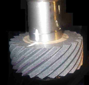
Using grinding spindle speeds up to 15,000 rpm creates high metal removal rates, with tool speeds up to 40 meters/second. This results in productive internal gear grinding process that is economical for mass production. By comparison, the typical honing process for internal gears has a tool speed of approximately 5 meters/seconds. The reported consumable tool cost for honing internal gears using diamond coated tools is three to six times higher than generating internal gear grinding. In the prototype gear manufacturing environment, the ability to make profile angle adjustments (fHɑ) during production is valuable. Complete multi-axis control of the internal generating process permits symmetrical and asymmetrical pressure angle adjustment, as well as barreling (involute crowning) and tip relief via dresser micro-geometry. Helix taper and fHβ are also adjustable via on-screen operator controls.
Conclusion
Runout, or Fr, is a common quality concern for manufacturers of internal ring gears as this is a typical result of heat treatment. Huge improvement is possible with generating internal gear grinding. A recent test showed pre-grind Fr values in the 0.092 mm range reduced to 0.009 mm. This represents an approximate quality improvement for this characteristic from ISO 10 to ISO 4. With the aforementioned green processes, higher quality gears after heat treat are achievable with internal generative gear grinding. MHI is uniquely qualified to supply and support broaching, gear skiving and shaping on the green end as well as generative internal gear grinding after heat treatment.Nidec Machine Tool America LLC
Phone: (248) 669-6136


